SonTek/YSI
2
ADVField Operation Manual (September 1, 2001)
• Splash-Proof Housing: The typical ADVField processor in this configuration consists of three
printed circuit (PC) cards enclosed in a splash-proof container (22x11x7 cm; 8.5x4.5x2.8 in).
The housing is safe from incidental water contact, but should not be submerged. There are
four external connectors on the housing: one to the probe, one for serial communication with
the controlling computer, one for DC power input, and one for auxiliary input/output functions
(analog output voltages and external synchronization).
Splash-proof systems can also be equipped with an optional rechargeable battery (§4.5), which
provides 8 hours of operating power. The size of the splash-proof container for this option is
32x11x7 cm (12.5x4.5x2.8 in).
• Underwater Canister: The typical ADVField processor in this configuration consists of three
printed circuit (PC) cards enclosed in a submergible housing. In the underwater canister, the
processor may include an optional card for internal data recording and internal battery packs
for autonomous operation. Three housings are available for different system configurations – a
rectangular housing for real-time systems (15x15x25 cm; 5.8x5.8x9.8 in), a cylindrical hous-
ing for real-time systems (17-cm dia. x 32-cm tall; 6.6x12.5 in), and a cylindrical housing with
batteries for autonomous deployment (17-cm dia. x 72-cm tall; 6.6x28.5 in).
Underwater canister systems, including all cables and connectors, can be operated when fully
submerged. There are two or three (depending on external sensors) external connectors on the
underwater canister: one to the probe, and the other to a multi-purpose cable for DC power
(e.g., to an external battery canister), serial communication, and auxiliary input/output func-
tions (analog output voltages and external synchronization). The ADVField processor in the
underwater canister can include a compass/tilt sensor mounted inside the canister; this sensor
may also be mounted in the probe housing as described in the following paragraphs.
1.1.2. 16-MHz MicroADV Probe and 10-MHz ADV Probe
Note: The 16-MHz MicroADV Probe (Figure 2) is identical in both form and function to the 10-
MHz ADV Probe. The difference between the two is the acoustic frequency, the sampling rate,
and the sampling volume. Table 1 compares the three major ADV models. Unless specifically
identified, the descriptions in this section apply to both the 16-MHz MicroADV Probe and the
10-MHz ADV Probe.
The 16/10-MHz ADV probe configurations are divided into two groups: with or without optional
sensors (compass/tilt, pressure, and temperature). Within these groups are several sensor configu-
rations. The 16/10-MHz ADV probe is used for field measurements where shallow-water opera-
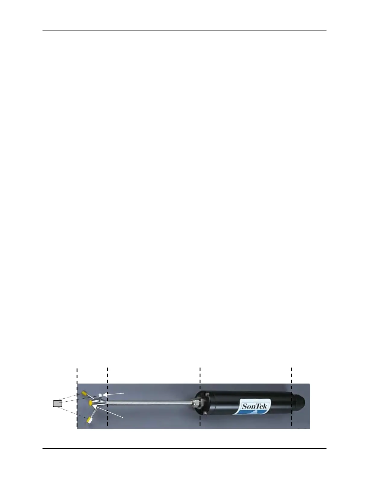
tion or high spatial resolution is required. Figure 2 shows the standard 16/10-MHz ADV probe.
Fi
ure 2 – T
ical ADVField Probe
both 16-MHz and 10-MHz
Acoustic
Sensor
Stem Signal Conditioning Module
Underwater
Connector
Sampling
Volume
Transmitter (1)
Receivers (3)

 Loading...


