SonTek/YSI
ADVField/Hydra Operation Manual (September 1, 2001) 3
Parameter 16-MHz MicroADV 10-MHz ADV 5-MHz ADVOcean
Sampling rate (Hz) 0.1 to 50 0.1 to 25 0.1 to 25
Sampling volume (cc) 0.09 0.25 2.0
Distance to sampling volume (cm) 5 5 or 10 18
Resolution (cm/s) 0.01 0.01 0.01
Programmable velocity range (cm/s) 3, 10, 30, 100, 250 3, 10, 30, 100, 250 5, 20, 50, 200, 500
Accuracy 1% of measured velocity, ±0.25 cm/s
16/10-MHz Probe Configuration without Optional Sensors:
• The acoustic sensor (Figure 3) consists of two or three acoustic receivers (for 2D or 3D
probes) and one acoustic transmitter. The sensor can be mounted on a stainless steel stem (25
or 40-cm long) or on a 100-cm flexible cable. The acoustic sensor can be oriented looking
down, to the side (mounted on a 90° adapter), or up (with a bent stem and a 90° adapter).
• The sampling volume is the volume of water (≈0.3 cm
3
) in which the ADV makes velocity
measurements. Depending on probe configuration, this volume is nominally located either
5 cm or 10 cm (10-MHz systems only) from the acoustic transmitter.
• The standard 16/10-MHz ADV probe consists of the acoustic sensor, the stem (or cable), and
the end cap attached to the signal-conditioning module. The probe serial number is stamped
on the end cap. For probes that will be deployed in saline environments, a sacrificial zinc an-
ode is attached to the stem for corrosion protection.
• The probe coordinate system (§5.1) depends on the probe configuration.
• The signal-conditioning module is a cylindrical Delrin housing with internal receiver electron-
ics. The probe is mounted at one end of the Delrin housing, while the other end cap is con-
nected to a high-frequency cable using a 16-pin wet-mateable connector. The signal condition-
ing module is 5.3 cm (2.09 in) in diameter by 28.5 cm (11.2 in) long. The dimensions of the
probe vary with 2D and 3D probes, distance to the sampling volume, stem or cable length, and
sensor orientation.
• The high-frequency cable to the processing module carries analog signals from the probe to
the digital processing electronics. This cable is highly sensitive to noise and should not be
modified without instruction from SonTek. The cable is connected to the signal-conditioning
module using a 16-pin wet-mateable connector.
Table 1. ADVField Processing Comparison (based on acoustic frequency)
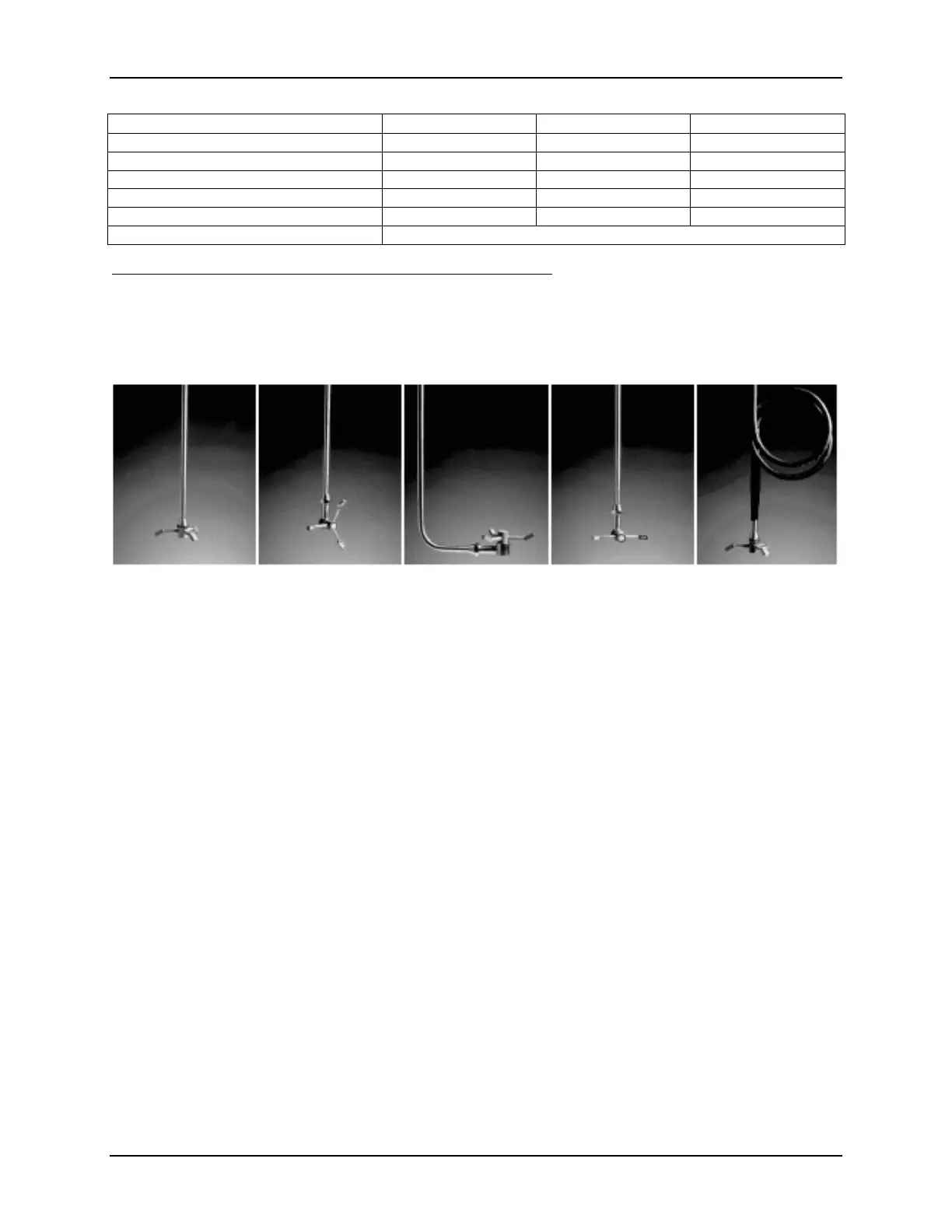
Figure 3 – Probes: (a) Down-looking 3D, (b) Side-looking 3D, (c) Up-looking 3D,
(d) Side-Looking 2D, (e) Cable-Mounted

 Loading...


