SonTek/YSI
ADVField/Hydra Operation Manual (September 1, 2001) 49
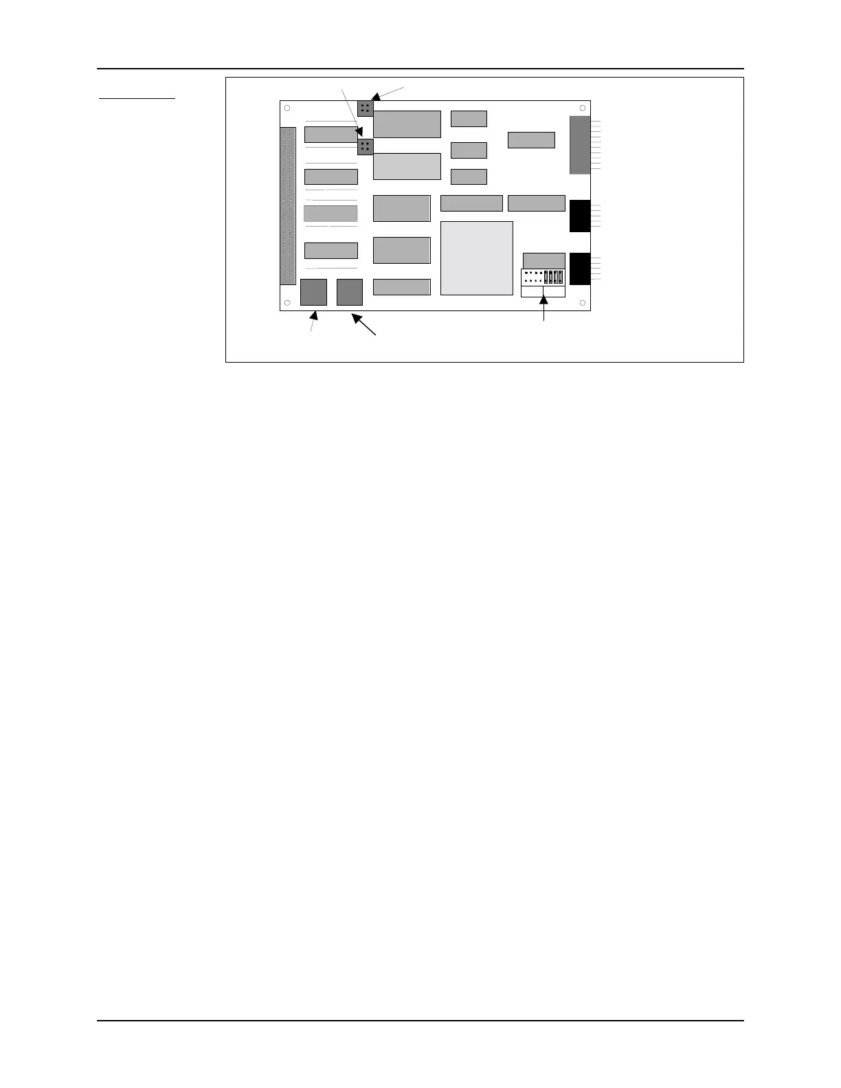
CPU Board
Figure 11 shows
the layout of the
CPU board with a
few important fea-
tures labeled. The
CPU provides the
overall control of
ADV operation
including data
collection, user
interface, com-
pass, and recorder
control. Important
features include:
• CPU – The central processing unit controls all major ADV functions and peripherals including
data collection, user interface, compass, and recorder.
• CPU EPROM – This chip stores the algorithms used to control ADV operation. Upgrades for
this EPROM may be available periodically. See §4.4.7 for replacement instructions.
• Compass Connector – The keyed, 10-pin, red connector carries power and serial communica-
tions to/from the optional compass/tilt sensor. The cable from this connector goes to the probe
cable (when the compass/tilt sensor is installed in the conditioning module) or directly to the
compass (when installed in the underwater canister).
• Second Serial Port – The keyed, 10-pin, black rectangular connector is used only if an optional
device is installed (e.g., CTD, serial Paros pressure sensor, LISST, etc.)
• Serial Communication Connector – The keyed, 10-pin, black rectangular connector carries the
serial communications signals for the external user interface. This is the same connector type
as the spare connector listed above. The cable from this connector goes to the DB9 serial
communications connector (ADVField in splash-proof housing) or to the power and commu-
nications connector (ADVField in underwater canister).
• Full-Length Card Connector – This 64-pin connector mates to a connector on the DSP board
and to a connector on the Recorder board.
• Baud Rate Hex Switch – This rotary switch sets the serial communication baud rate. The
switch can be accessed while the processing module is assembled. Defaults: 9600 (for firm-
ware v6.8 and earlier); 19200 (firmware after v6.8). See §4.2 for details on switch settings.
• Address Hex Switch – This rotary switch sets the system address for RS485 communication.
The default is 0 (for RS232 or RS422). The switch is positioned so it can be accessed while
the processing module is assembled. See §4.2 for details on switch settings.
• Serial Communication Jumpers – These jumpers are used to select the serial communication
protocol; the default is RS232. The jumpers cannot be accessed while the processing module
is assembled. See §4.2 for details.
• Jumpers J1 and J2 – These jumpers are not used and should be left open (no pins connected).
Compass
Connector
SONTEK INC. ADF CPU CARD REV. D 12/95 MADE IN
CPU
CPU
EPROM
Full Length
Card Connector
Second Serial Port
for CTD, Serial
Paros, LISST, etc.
Serial Communication
Connector
BAUD ADDRESS
232
422/48
Baud Rate
Hex Switch
Address
Hex Switch
Serial Communication
Jum
ers
Jumper J1
Jumper J2
Figure 11 - ADVField CPU Board

 Loading...


