INSTRUMENT DESCRIPTION
Carl Zeiss Operation and Functional Elements of Optional Components Axio Vert.A1
36 431030-7044-001 05/2012
2.6.2 Microscope Stages
Mechanical Stage 130x85 R/L with Short
Coaxial Drive
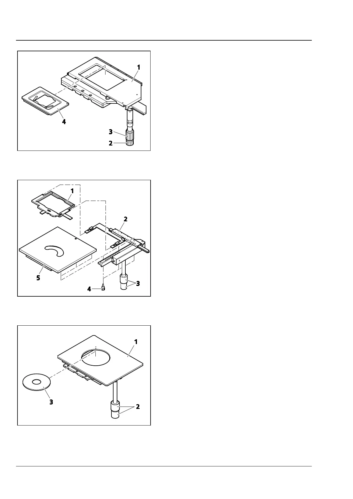
− Mechanical stage (Fig. 2-14/1) designed to
hold and position specimens in mounting
frame K (Fig. 2-14/4)
− To insert the mounting frame, put the
mounting frame corner marked with a red
dot into the recess of the mechanical stage.
Press the frame diagonally onto the springs
and downward into the recess. In so doing,
make sure that the mounting frame is
correctly seated.
− Drive knobs for X (Fig. 2-14/2) and Y
adjustment (Fig. 2-14/3)
− The mechanical stage with coaxial drive can
be fitted on the right-hand or left-hand side
of the stand.
Specimen Stage 232x230 to Which an
M 130x85 mm Object Guide Can Be Attached
− Specimen stage (Fig. 2-15/5) designed to
hold and position specimens for transmitted
light and reflected light
− With the object guide (Fig. 2-15/2) attached,
this stage is capable of holding specimens in
mounting frame Flex M (Fig. 2-15/1) and
mounting frame inserts for Petri dishes or
object slides and chambers, as well as
accommodating mounting frame M from the
current product line.
− Coaxial drive (Fig. 2-15/3) designed to
position the mounting frame in XY
− To attach the object guide to the right-hand
or left-hand side of the stage, set the guide
onto the stage from below and secure it
firmly in place with the screws supplied
(Fig. 2-15/4).
Mechanical Stage 40x40 for Reflected Light
− Mechanical stage (Fig. 2-16/1) designed to
hold and position reflected light specimens,
equipped with coaxial drive (Fig. 2-16/2) for
XY adjustment
− The mechanical stage with coaxial drive can
be fitted on the right-hand or left-hand side
of the stand.
− Suitable for use with d = 115 mm stage
inserts (Fig. 2-16/3).
Fig. 2-14 Mechanical Stage 130x85 R with
Mounting Frame
Fig. 2-15 Specimen Stage 232x230 and
Object guide M 130x85 mm
Fig. 2-16 Mechanical Stage 40x40 for
Reflected Light with Stage Insert