PUTTING THE INSTRUMENT INTO OPERATION
Axio Vert.A1
Mounting Standard Components Carl Zeiss
05/2012 431030-7044-001 45
3.1.6.3 Mounting the Scanning Stage
To mount scanning stage 130x85 motP; CAN, follow the same procedure as for the mechanical stage.
In addition, heed the suggestions below when mounting the scanning stage.
• After mounting the stage on the stand, screw
out the transport lock pin (Fig. 3-8/1) located on
the underside of the stage.
Be sure to screw the transport lock
pin in again whenever you transport
the stage.
The traversing ranges of the scanning stage in X
and Y directions may be restricted in the following
way if necessary:
X direction
• In order to change the right or left stop for the
X direction, loosen the relevant stop screw
(Fig. 3-8/2) on the underside of the stage, move
the screw into the desired position and
retighten it.
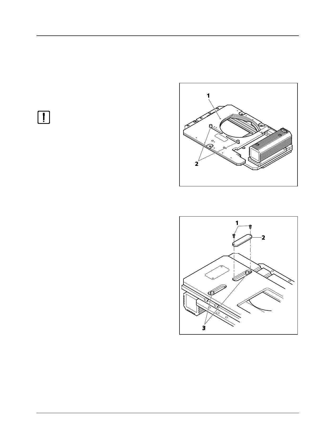
Y direction
• In order to change the front or rear stop for the
Y direction, first turn out the screws (Fig. 3-9/1)
of the covers on the upper side of the stage and
remove the covers (Fig. 3-9/2).
• Then loosen the stop screws (Fig. 3-9/3), move
the screws in the desired position and retighten
them.
• Next, screw the covers back on again.
Fig. 3-8 Underside of the Scanning Stage
Fig. 3-9 Upper Side of the Scanning Stage