OPERATION
Carl Zeiss Illumination and Contrast Techniques in Transmitted Light Axio Vert.A1
80 431030-7044-001 05/2012
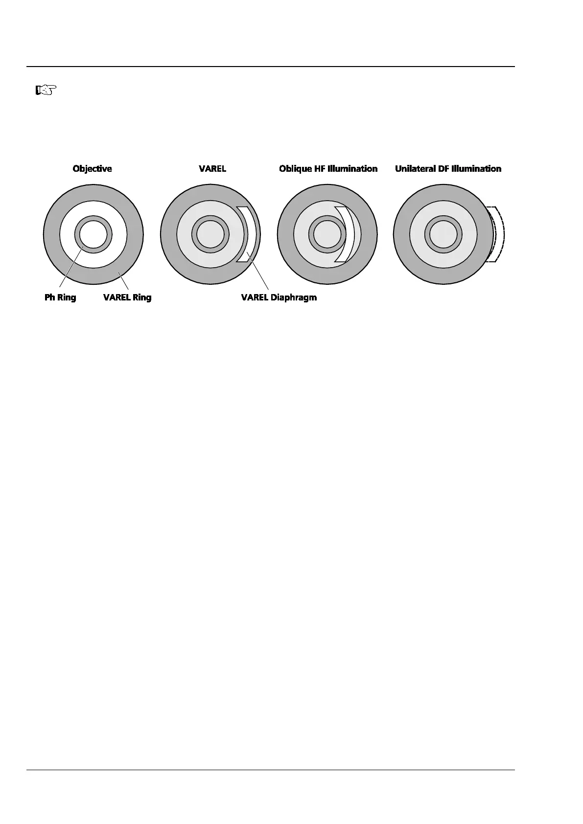
Fig. 4-7 VAREL Contrast Pupil Images
4.11.4 Transmitted Light Differential Interference Contrast (DIC)
The transmitted light DIC technique permits a high-contrast, plastic imaging of transparent specimen
details. The light linearly polarized by a polarizer is split into two partial beams in a birefringent prism.
These beams pass through two neighboring areas of the specimen at a close distance and experience
path differences there due to differences in refractive index and specimen thickness. The two partial
beams are subsequently merged in a second birefringent prism and end up with the same vibration
direction after passing through the analyzer. Consequently, the two partial beams can interfere with one
another in the intermediate image, with the path differences resulting in different gray values
(intensities).
Requirements
− The microscope must have properly been put into operation, as described in Section 3.
− The microscope must be switched on.
− Condenser 0.4 with modulator disk and built-in DIC I/0.4 or DIC II/0.4 condenser module
or
condenser 0.55 with modulator disk and built-in DIC I/0.55, DIC II/0.55 or
DIC III/0.55 condenser module (Each condenser module comes with a built-in polarizer.)
− Objectives for DIC contrast
− DIC slider matching the objectives used
− D P&C analyzer module in the reflector turret or three-position contrast slider (10 mm x 29 mm) with
built-in analyzer for the contrast slider
− Specimen vessel with glass bottom
Moving the VAREL illumination all the way to a position outside of the pupil corresponds to
unilateral DF illumination.
Moving the VAREL illum
ination between the Ph and VAREL rings of the objective
corresponds to oblique HF illumination.