PUTTING THE INSTRUMENT INTO OPERATION
Carl Zeiss Mounting Optional Components Axio Vert.A1
66 431030-7044-001 05/2012
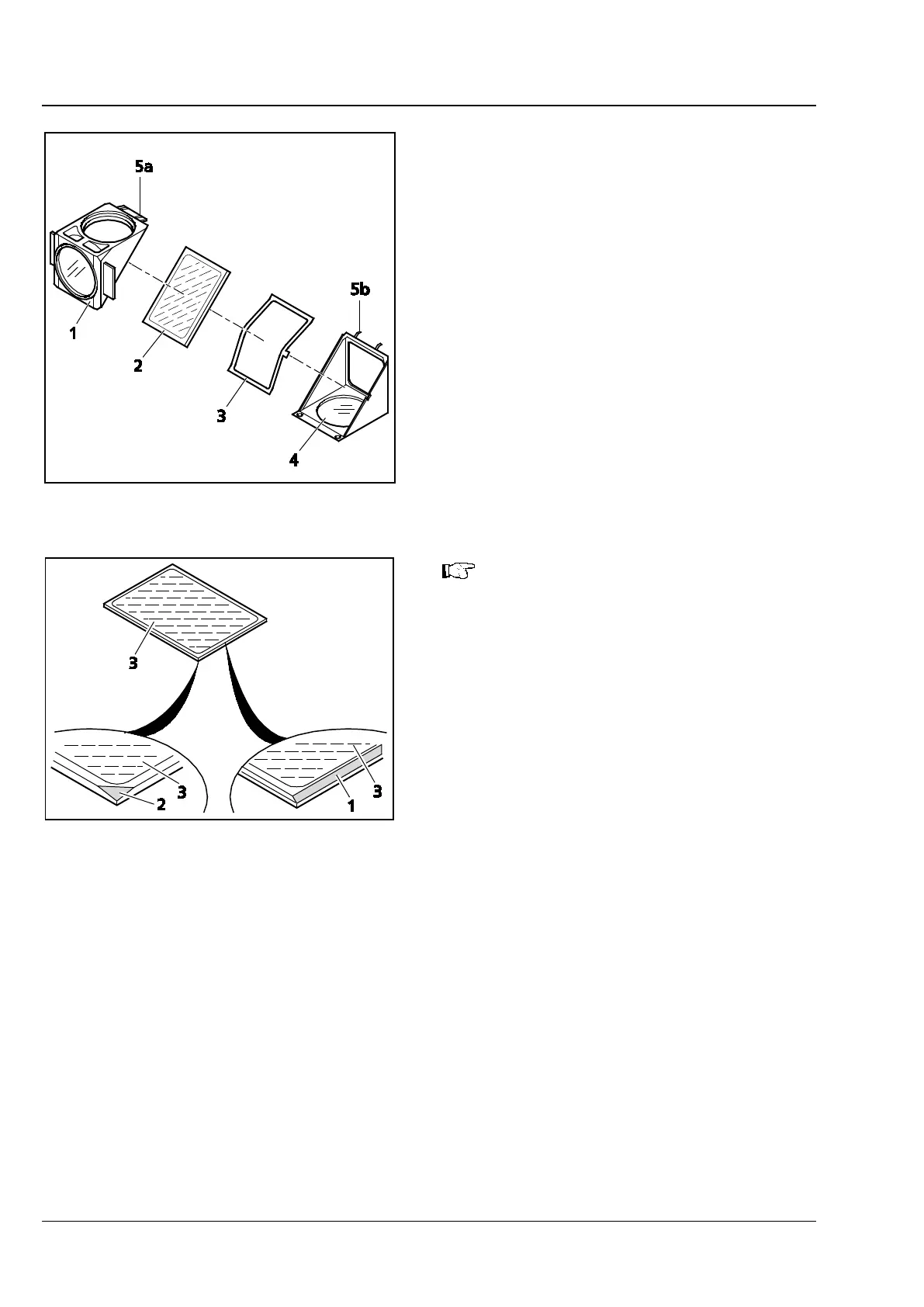
• Tilt the excitation module half (Fig. 3-31/1),
which is now on top, upward and lift it out of
the retaining elements (Fig. 3-31/5b) of the
lower emission module half (Fig. 3-31/4).
• Take the beam splitter (Fig. 3-31/2) and the
spring frame (Fig. 3-31/3) out of the lower
module half.
• Remove the old beam splitter and carefully put
the new one on the spring frame (Fig. 3-31/3),
with the reflecting side facing upward. Then
place the two parts together into the lower
module half. Make sure that the tongue of the
frame sits in the relevant recess of the lower
module half.
The reflecting (coated) side
(Fig. 3-32/3
) of the beam splitter is
provided with a beveled edge
(Fig. 3-32/1) or corner (Fig. 3-32/2).
• Place the excitation module half (Fig. 3-31/1)
on the emission module half (Fig. 3-31/4). The
retaining elements (Fig. 3-31/5b) and the eyes
(Fig. 3-31/5a) must engage. Hold the two
halves together and turn them over, so that
they are in the mounting position again.
• Reinsert and tighten the slotted screws.
• Then attach the sticker, identifying the filter
combination, to the side of the module.
Fig. 3-31 Changing the Beam Splitter
Fig. 3-32 Identification Features of the Beam
Splitter