PUTTING THE INSTRUMENT INTO OPERATION
Axio Vert.A1
Mounting Standard Components Carl Zeiss
05/2012 431030-7044-001 49
3.1.9 Equipping the Reflector Turret
The reflector turret is fixed-mounted in the Axio Vert.A1 FL, Axio Vert.A1 FL-LED and Axio Vert.A1 MAT
stands.
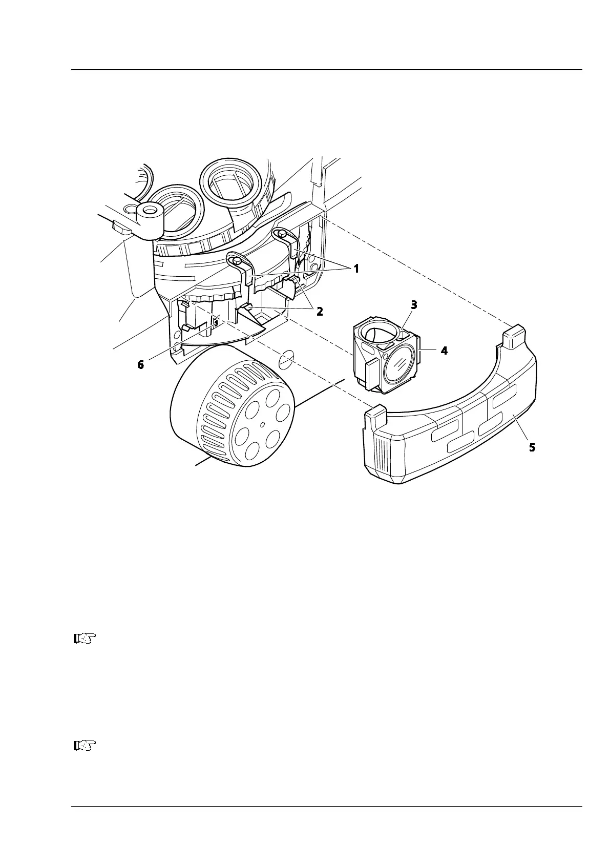
Fig. 3-12 Equipping the Reflector Turret
• Pull the protective cover (Fig. 3-12/5) off to the right.
• In the desired order, insert reflector modules, fitted with filter sets (Fig. 3-12/3), into the relevant
reflector turret position (see position marking in Fig. 3-12/6), starting at position 1 (emission filter in
bottom position). For this purpose, first insert the reflector module in an inclined position from below,
with the locating elements (Fig. 3-12/4) on the right-hand and left-hand sides, into the two upper
clamping springs (Fig. 3-12/1). Then press the module against the lower clamping springs (Fig. 3-12/2)
from the front until the module is safely locked in place.
While inserting the module, make certain that it does not get jammed and that you press it
securely against the upper stop.
• To remove a reflector module that is no longer needed, first pull the module out of the lower spring
clamps and then out of the upper spring clamps.
• Plug on the protective cover.
• Stick the adhesive labels specifying the filter combinations utilized for each reflector turret position to
the spaces provided on the protective cover.
For the insertion and changing of filter sets or beam splitters, see Section 3.3.3 and 3.3.4,
respectively.