OPERATION
Carl Zeiss Illumination and Contrast Techniques in Transmitted Light Axio Vert.A1
76 431030-7044-001 05/2012
4.11 Illumination and Contrast
Techniques in Transmitted Light
Every Axio Vert.A1 stand version
allows the user to apply the transmitted light
methods described below (Axio Vert.A1 MAT with
optional transmitted light illumination only).
4.11.1 Transmitted Light Bright Field
Requirements
− The microscope must have properly been put
into operation, as described in Section 3.
− The microscope must be switched on.
Setting Bright Field
• Check the position of the TL/RL switch and shift
it to the TL position if necessary.
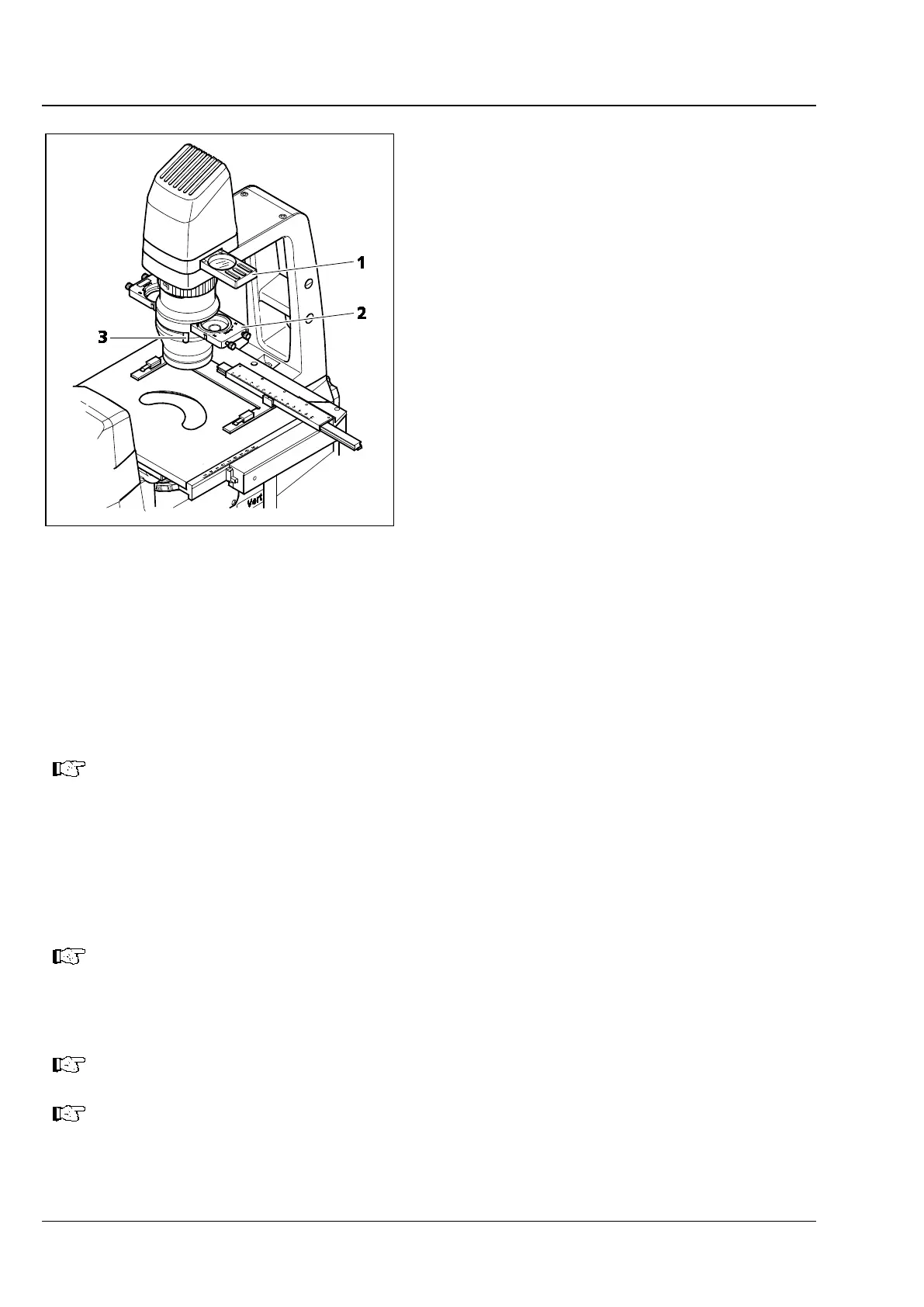
• Move the center position on the slider (Fig. 4-2/2) of the condenser or the position for bright field on
the condenser with modulator disk into the light path.
• Place the specimen on the specimen stage and use the focusing drive to lock focus at low
magnification (e.g., objective 10x, yellow ring).
• Use the lever (Fig. 4-2/3) or the setting wheel to close the aperture diaphragm until optimum contrast
is obtained.
The aperture diaphragm is not meant to adjust image brightness (loss of image quality).
• If required, adjust illumination intensity by turning the on/off control button or inserting the
attenuation filter into the filter slider (Fig. 4-2/1) and moving it into the light path.
Use of a conversion filter and a shutter plate is recommended when you employ the LED lamp for
transmitted light illumination. To this end, insert the conversion filter and the shutter plate into the
positions of the filter slider.
When used with transmitted light LED illumination, the conversion filter creates the usual
daylight impression during the microscoping process. Without that fil
appear slightly bluish
on occasion. Do not employ the conversion filter when transmitted
light HAL illumination is installed, as HAL might damage the filter as a result of the heat
generated.
In order to avoid veiling glare during FL viewing, be sure to fit the supplied shutter plate in
the second position of the slider in the carrier to block the light path temporarily.
The bright field position of sliders for condensers is fitted with a neutral-density filter to
ensure that, in the event of a contrast change, brightness is adjusted to phase contrast, for
instance.
Fig. 4-2 Setting Bright Field