PUTTING THE INSTRUMENT INTO OPERATION
Axio Vert.A1
Mounting Optional Components Carl Zeiss
05/2012 431030-7044-001 65
If the installation of filters not provided with
direction markings (arrows) proves necessary, we
recommend that the procedure below be followed:
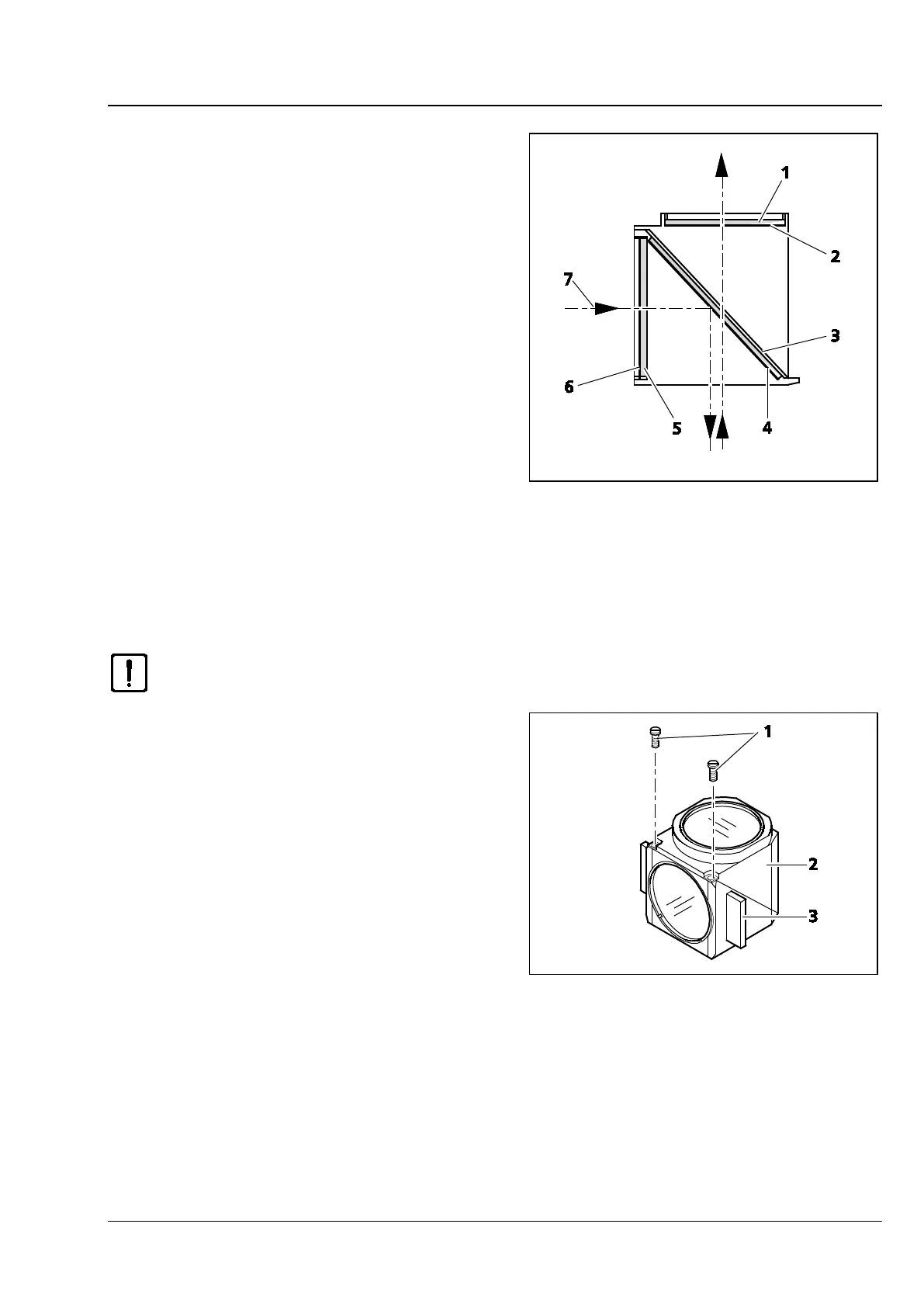
Be sure to install filters with reflecting, dielectric
layers in such a way that the reflecting layer
(Fig. 3-29/6) in the excitation filter (Fig. 3-29/5)
points outward (in relation to the reflector
module). In the barrier filter (Fig. 3-29/1), the
reflecting layer(Fig. 3-29/2) must point inward
(Fig. 3-29).
In mounting position, the reflecting layer
(Fig. 3-29/4) of the beam splitter (Fig. 3-29/3) must
point downward.
The arrows (Fig. 3-29/7) mark the illumination
beam path or the imaging beam path.
3.3.4 Changing the Beam Splitter in the FL P&C Reflector Module
Please, proceed with utmost care in mounting the filters and the beam splitter to avoid
damaging and soiling optical components.
We recommend that you order fully fitted FL P&C
reflector modules from Carl Zeiss, as changing the
beam splitter is a demanding operation.
Proceed as follows when changing the beam
splitter:
• Remove the FL P&C reflector module from the
reflector turret. (See also Section 3.1.9.)
• Loosen the two slotted screws (Fig. 3-30/1) with
a screwdriver.
• Hold the two reflector module halves -
emission module half (Fig. 3-30/2) and
excitation module half (Fig. 3-30/3) together,
turn them over against the mounting position
and set them down.
Fig. 3-29 Installing Filters and Beam Splitters
Fig. 3-30 Opening the Reflector Module