Configuring the traffic interfaces | 102
3. Set the DFXO Input Level and the Output Level required:
Signal Direction Level adjustment range Default setting
Input Level (L
i
) -10.0 dBr to +1.0 dBr in 0.5 dB steps -4.0 dBr
Output Level (L
o
) -10.0 dBr to +1.0 dBr in 0.5 dB steps -1.0 dBr
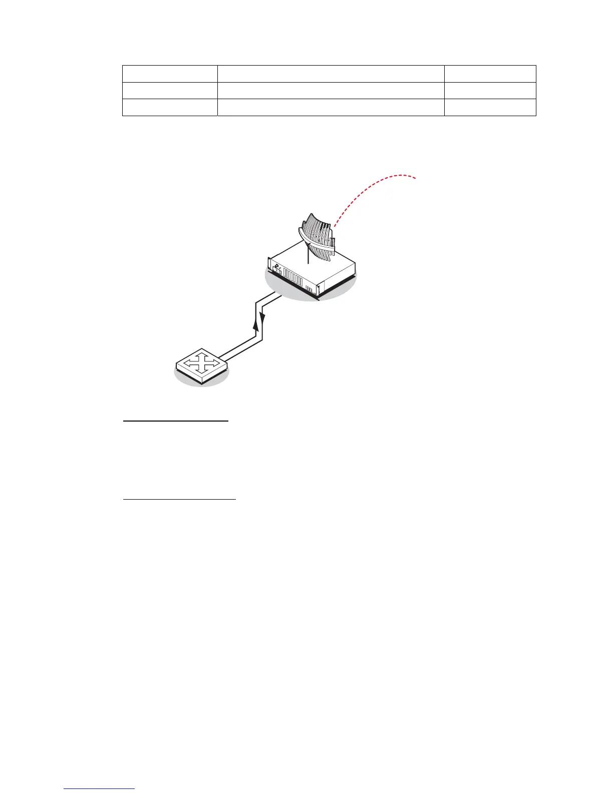
In the example shown below, the PSTN exchange line card is connected to a DFXO card.
The levels are set based on the system using a 0 dBr transmission reference point.
Output level
-6.0 dBr
Input level
+1.0 dBr
Output level
-1.0 dBr
Input level
-4.0 dBr
Transmission Reference point
0 dBr
DFXO Input Level setting
The exchange line card has a nominal output level of -6 dBr. To achieve a digital reference point
transmit level of -2.0 dBm0, the DFXO input level is set to -4.0 dBr (effective T pad gain of 4.0 dB).
The deliberate 2 dB of loss between the exchange line card and the DFXO provides a 2 dB of
overall circuit loss between the DFXO and the DFXS.
DFXO Output Level setting
The exchange line card has a nominal input level of +1.0 dBr. With a transmission reference point
received level of -2.0 dBm0, the DFXO output level is set to -1.0 dBr (effective R pad loss of 1.0
dB).
The deliberate 2 dB of loss between the exchange line card and the DFXO provides a 2 dB of
overall circuit loss between the DFXS and the DFXO.
4. Click Apply to apply changes or Reset to restore the previous configuration.