Protected terminals | 154
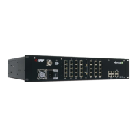
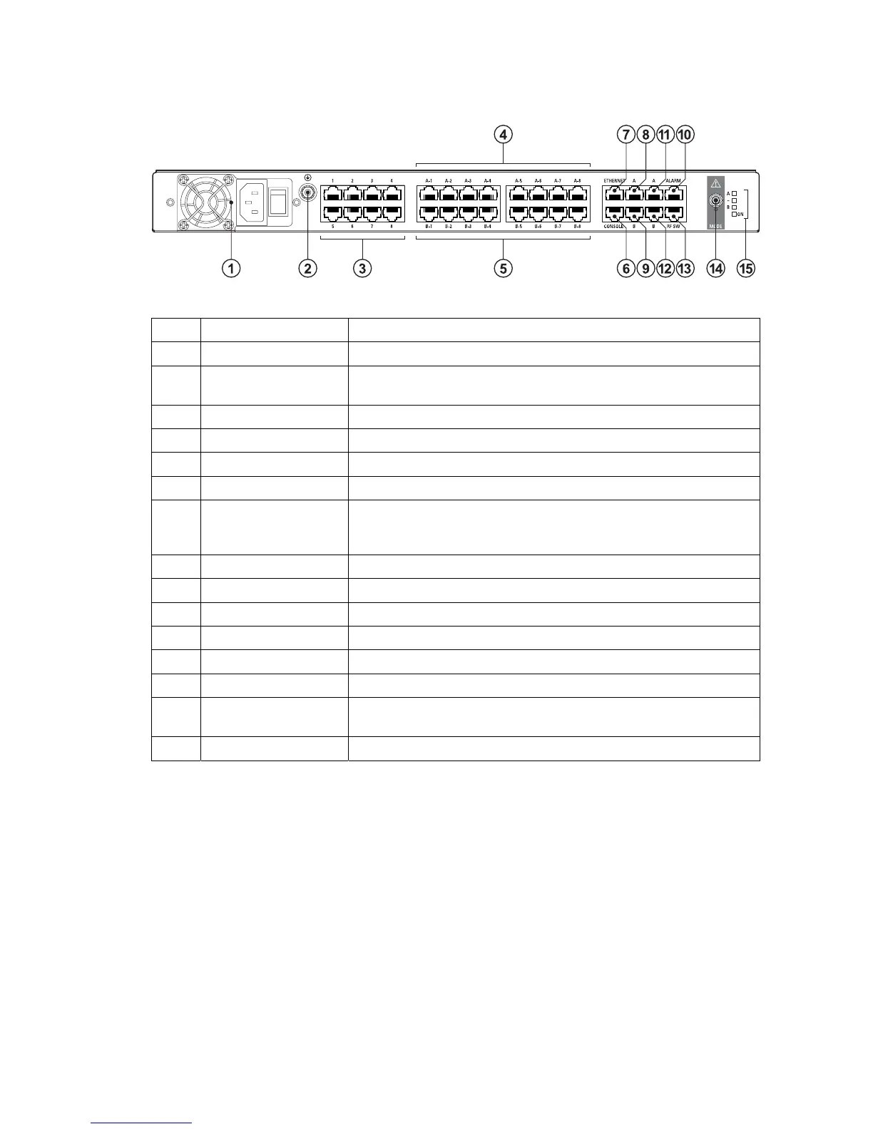
Tributary switch front panel
No. Description Explanation
1 Power supply input Input for DC power or AC power
2 Protective earth M5 terminal intended for connection to an external protective
conductor for protection against electric shock in case of a fault
3 Interface ports Port for connecting to customer interface equipment
4 Radio A interfaces These connect to the interface ports on radio A
5 Radio B interfaces These connect to the interface ports on radio B
6 Console For factory use only
7 Ethernet Port for connecting to customer Ethernet network. This port is also
used to set up and manage the radios remotely over an IP
network
8 Radio A Ethernet Connects to an Ethernet port on radio A
9 Radio B Ethernet Connects to an Ethernet port on radio B
10 Alarms Alarm input/output connections for customer equipment
11 Radio A alarms Connects to the alarm port on radio A
12 Radio B alarms Connects to the alarm port on radio B
13 RF SW Provides power and signalling to the RF switch
14 Mode switch Three-position locking toggle switch to set the MHSB switch into
automatic mode or radio A / radio B test mode
15 LEDs Mode and status LEDs