Configuring the traffic interfaces | 93
Circuit Levels
The 8 bit digital word for each analogue sample encoded (A law), has a maximum of 255 quantizing
code steps, + 127 for positive signals, -127 for negative signals and 0. A nominal level of 0 dBm
generates a peak code of ± 118 which allows up to +3.14 dBm0 of headroom before the maximum
step of 127 is obtained. Any level greater than +3.14 dBm0 will be distorted (clipped) which will cause
severe problems with analogue data transmission.
It is therefore important that analogue signals presented from the DFXO / DFXS line interface be
normalized to fit within the ± 127 quantizing steps. This is done by adjusting the circuit levels relative
to the 0 dBm (± 118 peak code) for example:
If a nominal input level of +1 dBm is applied to the DFXS line interface, the DFXS Input Level
must be set to +1.0 dBr. This will effectively attenuate the sent signal by 1 dB.
If a nominal output level of -6 dBm is required from the DFXS line interface, the DFXS Output
Level must be set to -6.0 dBr. This will effectively attenuate the received signal by 6 dB.
The circuit levels and the transhybrid loss of both ends of the circuit, also determine the stability of the
circuit. If the circuit levels are too high and the transhybrid loss figures achieved are too low, the circuit
can have a positive loop gain and can recirculate (sometimes called singing).
Typically, an end to end 2 wire voice circuit is engineered to have a 2-3 dB loss in both directions of
transmission.
2WS
2WR 2WS input
2WR output
0 dBr -6.0 dBr
+1.0 dBr
-8.0 dBm
+1.0 dBm
-2.0 dBm
0 dBr
0.0 dBm
-4.0 dBr
-1.0 dBr
-6.0 dBm
DFXS
Interface
DFXO
Interface
2WS
2WR
-6.0 dBr
+1.0 dBr
-1.0 dBm
0 dBr
0.0 dBm
0 dBr
-2.0 dBm
Exchange
Line Card
Aprisa XE
Overall Loss
= 3.0 dB
Overall Loss
= 8.0 dB
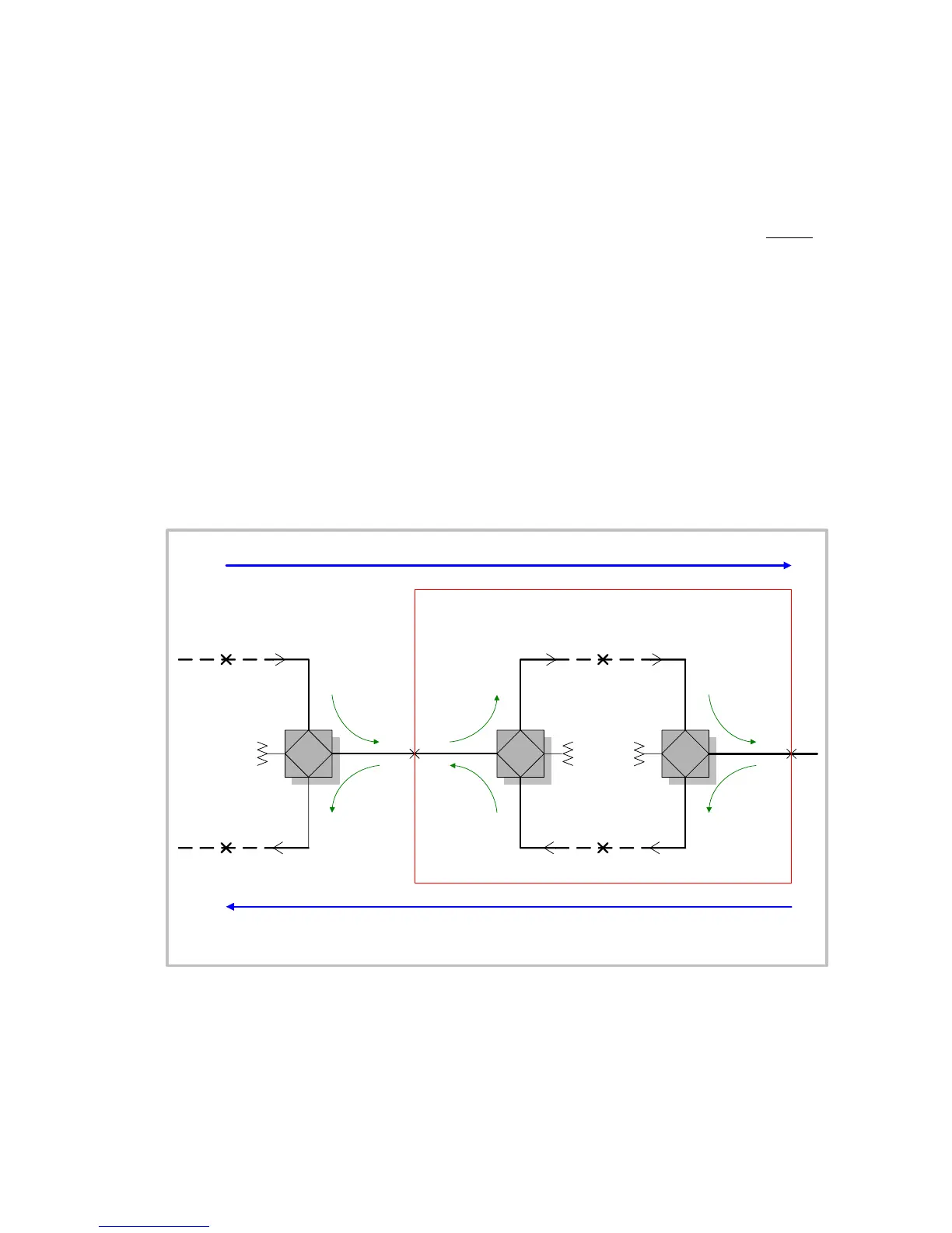
Derived System Level Plan
Note 1: The derived system loss is 2 dB in both directions due to the deliberate 2 dB level mismatch between
the exchange line card and the DFXO interface unit
Z
B
Z
B
Z
B
Transmission
Reference Point
4WR
4WS4WR
4WS4WR
4WS