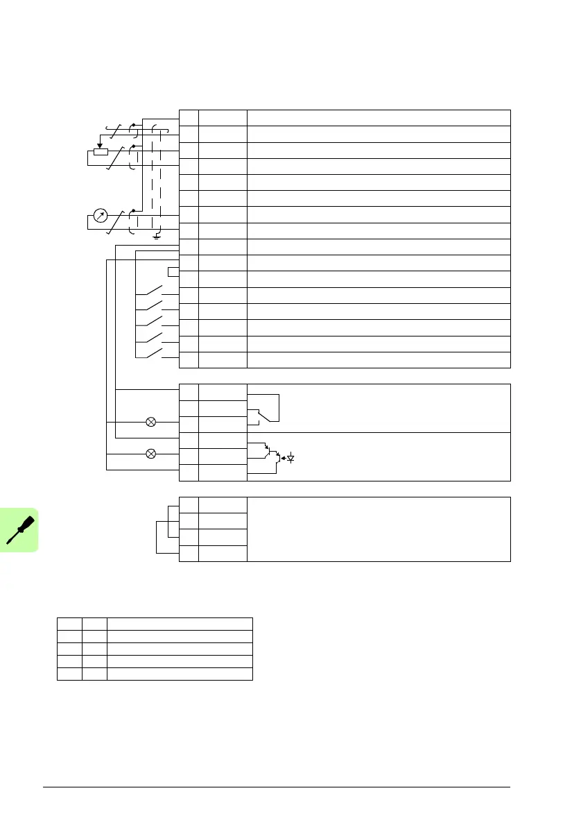
X1A
1 SCR Signal cable shield (screen)
2AI1 Output frequency reference: 0…10 V
1)
3 GND Analog input circuit common
4 +10V Reference voltage: +10 V DC, max. 10 mA
5 AI2 Not in use by default. 0…10 V
6 GND Analog input circuit common
7AO Output frequency value: 0…20 mA
8 GND Analog output circuit common
9 +24V Auxiliary voltage output: +24 V DC, max. 200 mA
10 GND Auxiliary voltage output common
11 DCOM Digital input common
12 DI1 Stop (0) / Start (1)
13 DI2 Forward (0) / Reverse (1)
14 DI3 Constant speed selection
2)
15 DI4 Constant speed selection
2)
16 DI5 Acceleration and deceleration selection
3)
X1B
17 ROCOM Relay output 1
No fault [Fault (-1)]
18 RONC
19 RONO
20 DOSRC Digital output, max. 100 mA
No fault [Fault (-1)]
21 DOOUT
22 DOGND
X1C:STO
1 OUT1 STO (Safe torque off) connection
2OUT2
3IN1
4IN2
max. 500 ohm
1…10 kohm
4)
1)
AI1 is used as a speed reference if vector mode is
selected.
2)
See parameter group 12 CONSTANT SPEEDS:
3)
0 = ramp times according to parameters 2202 and
2203.
1 = ramp times according to parameters 2205 and
2206.
4)
360 degree grounding under a clamp.
Tightening torque: 0.4 N·m / 3.5 lbf·in.

 Loading...


