Program features 75
Example
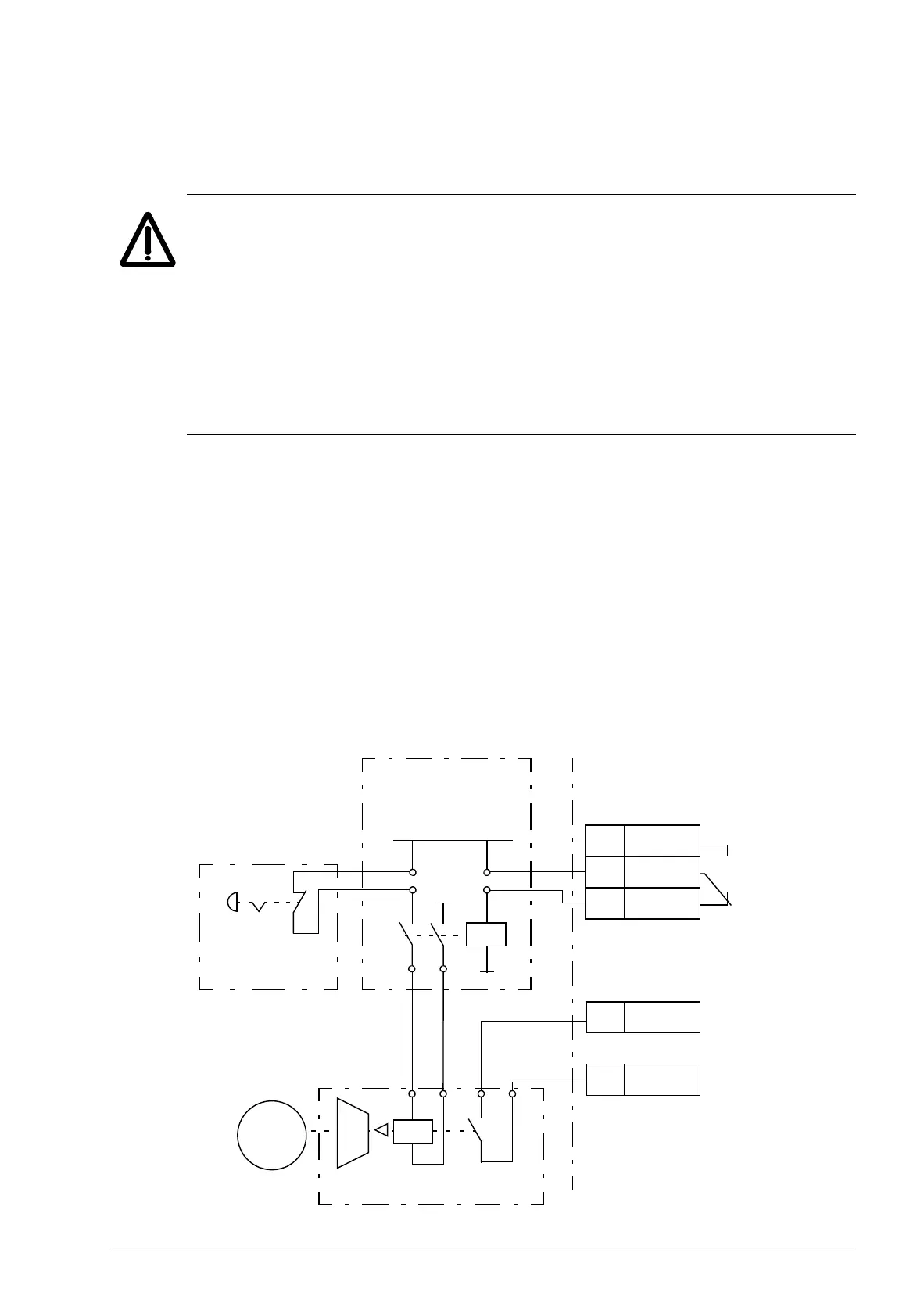
The figure below shows a brake control application example.
WARNING! Make sure that the machinery into which the drive with brake
control function is integrated fulfils the personnel safety regulations. Note
that the frequency converter (a Complete Drive Module or a Basic Drive
Module, as defined in IEC 61800-2), is not considered as a safety device
mentioned in the European Machinery Directive and related harmonised
standards. Thus, the personnel safety of the complete machinery must not
be based on a specific frequency converter feature (such as the brake
control function), but it has to be implemented as defined in the application
specific regulations.
Motor
M
230 VAC
JCU unit
Mechanical brake
Brake control
hardware
Emergency
brake
X2
1 RO1
2 RO1
3 RO1
X3
11 DI5
13 +24 V
The brake on/off is controlled via signal 03.16 Brake command. The source for the brake
supervision is selected by parameter 42.02 Brake acknowl.
The brake control hardware and wirings need to be done by the user.
• Brake on/off control through selected relay/digital output.
• Brake supervision through selected digital input.
• Emergency brake switch in the brake control circuit.
• Brake on/off control through relay output (i.e. parameter 14.42 RO1 src setting is
P.03.16.00 = 03.16 Brake command).
• Brake supervision through digital input DI5 (i.e. parameter 42.02 Brake acknowl setting is
P.02.01.04 = 02.01 DI status, bit 4)