318 Control through the embedded fieldbus interface
Basics of the embedded fieldbus interface
The cyclic communication between a fieldbus system and the drive consists of 16-bit
data words (with the ABB Drives profile or DCU 16-bit profile) or 32-bit data words
(with the DCU 32-bit profile).
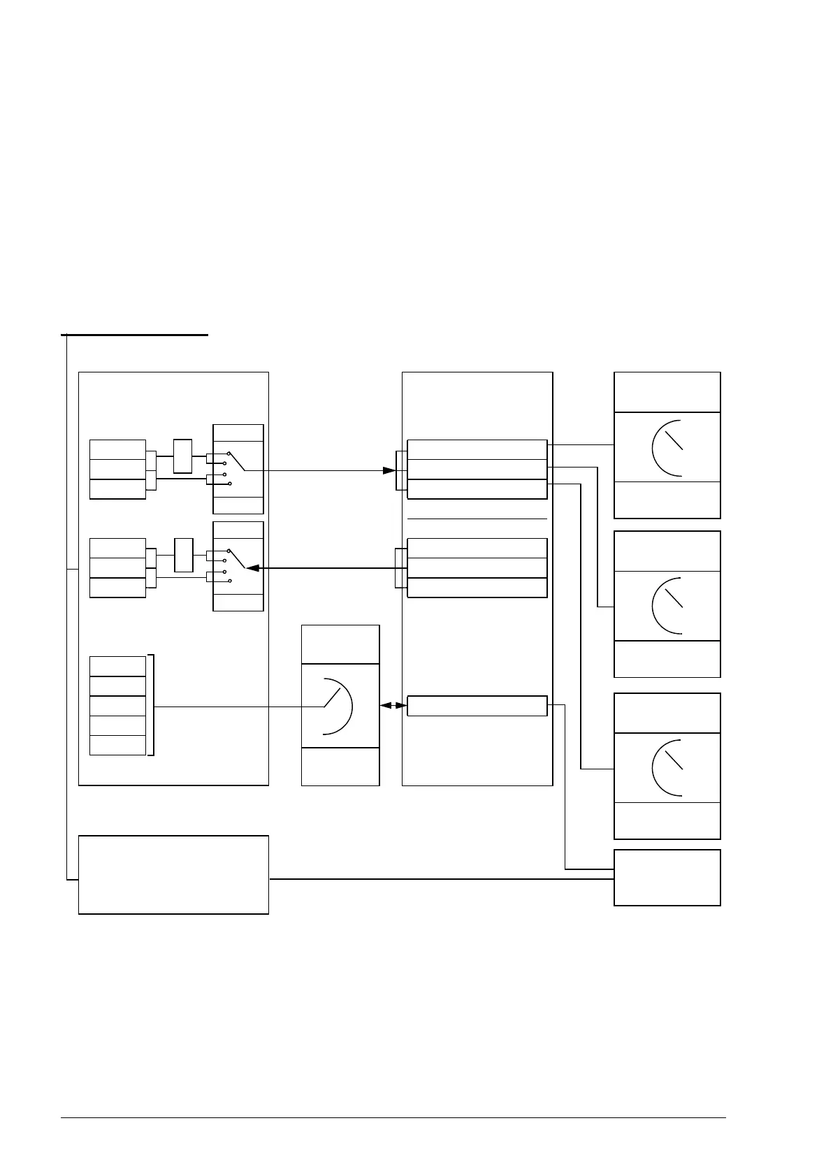
The diagram below illustrates the operation of the embedded fieldbus interface. The
signals transferred in the cyclic communication are explained further below the
diagram.
CW
REF1
REF2
SW
ACT1
ACT2
I/O 1
I/O 2
I/O 3
…
I/O 24
02.36 EFB main cw
02.38 EFB main ref1
02.39 EFB main ref2
02.37 EFB main sw
Actual 1
3)
Actual 2
3)
Par. 01.01…99.99
1) See also other parameters which can be controlled by the fieldbus.
2) Data conversion if parameter 58.06 Control profile is ABB Classic or ABB Enhanced. See section
About the EFB communication profiles on page 321.
3) See parameter 50.01 Fb ref1 modesel and 50.02 Fb ref2 modesel for the actual value selections.
1)
Fieldbus network
DATA I/O
selection
Group 58
EXT1/2
Start func
10.01
10.04
Speed/Torque
REF1 sel
21.01 / 24.01 /
24.02
Speed/Torque
REF2 sel
21.02 / 24.01 /
24.02
Cyclic communication
Acyclic communication
58.06
SEL
2)
Parameter
table
0
1
2
3
58.06
SEL
0
1
2
3
2)

 Loading...


