344 Control through a fieldbus adapter
Basics of the fieldbus adapter interface
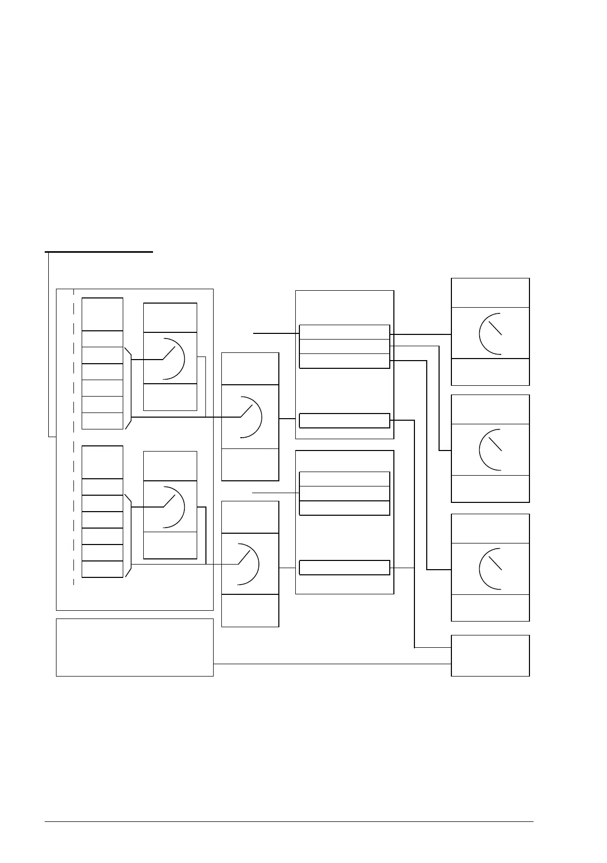
The cyclic communication between a fieldbus system and the drive consists of 16/32-
bit input and output data words. The drive supports at the maximum the use of 12
data words (16 bits) in each direction.
Data transmitted from the drive to the fieldbus controller is defined by parameters
52.01 FBA data in1 … 52.12 FBA data in12. The data transmitted from the fieldbus
controller to the drive is defined by parameters 53.01 FBA data out1 … 53.12 FBA
data out12.
DATA
OUT
2)
4)
1
2
3
…
12
DATA
IN
2)
5)
1
2
3
…
12
FBA MAIN SW
FBA ACT1
FBA ACT2
Par. 01.01…99.99
FBA MAIN CW
FBA REF1
FBA REF2
Par. 10.01…99.99
1) See also other parameters which can be controlled by the fieldbus.
2) The maximum number of used data words is protocol-dependent.
3) Profile/instance selection parameters. Fieldbus module specific parameters. For more
information, see the User’s Manual of the appropriate fieldbus adapter module.
4) With DeviceNet, the control part is transmitted directly.
5) With DeviceNet, the actual value part is transmitted directly.
3)
3)
Parameter
table
4)
5)
1)
Fieldbus network
Fieldbus adapter
Fieldbus-specific interface
Profile
selection
Profile
selection
DATA OUT
selection
Group 53
DATA IN
selection
Group 52
FBA Profile
EXT1/2
Start func
10.01
10.04
Speed/Torque
REF1 sel
21.01 / 24.01
/ 24.02
Speed/Torque
REF2 sel
21.02 / 24.01
/ 24.02
Cyclic communication
Acyclic communication
See the manual of the fieldbus
adapter module.

 Loading...


