Parameters 119
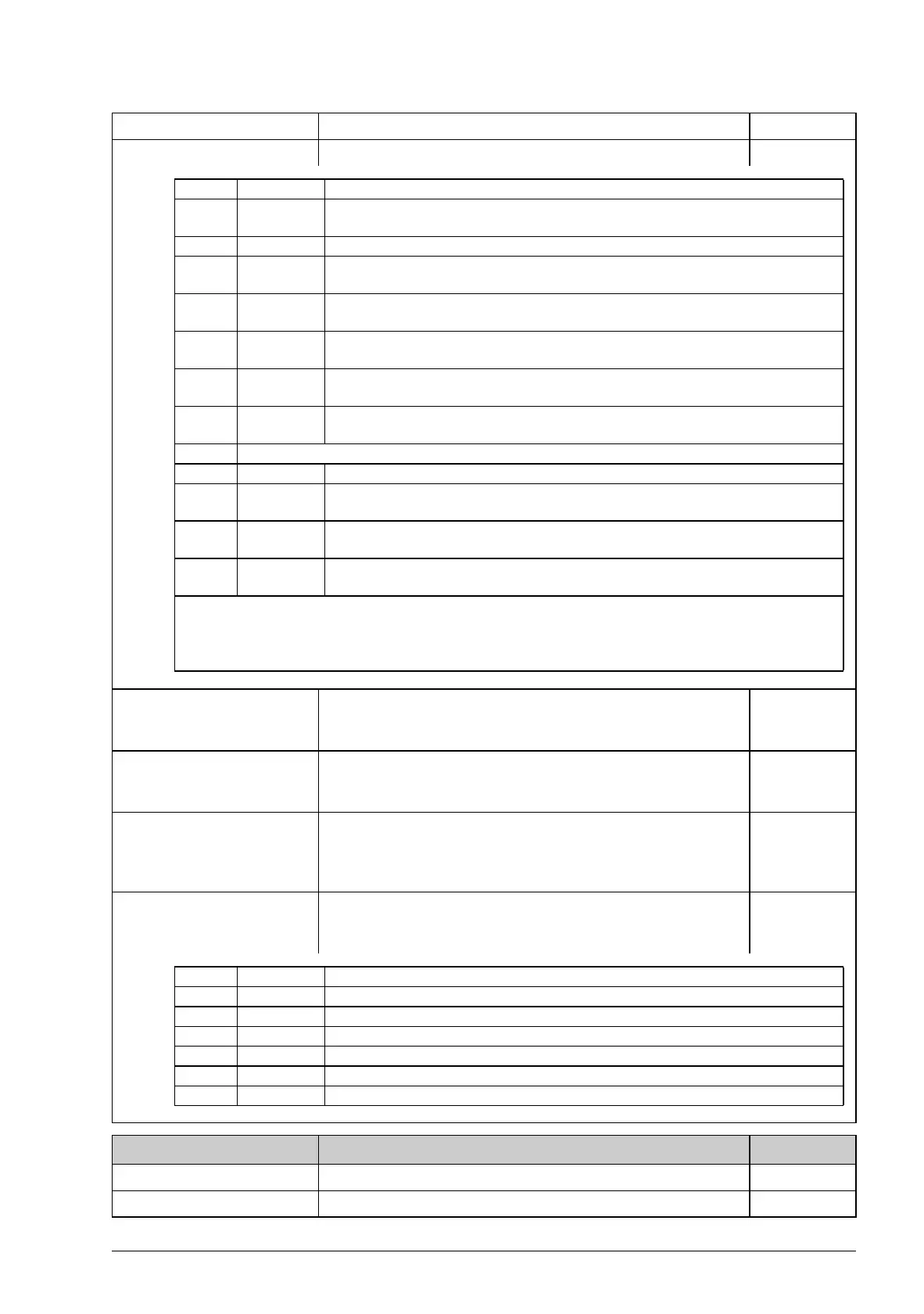
06.07 Torq lim status Torque controller limitation status word. -
06.12 Op mode ack Operation mode acknowledge: 0 = Stopped, 1 = Speed,
2 = Torque, 3 = Min, 4 = Max, 5 = Add, 10 = Scalar,
11 = Forced Magn (i.e. DC Hold)
1 = 1
06.13 Superv status Supervision status word. Bits 0…2 reflect the status of
supervisory functions 1…3 respectively. The functions are
configured in parameter group 33 Supervision (page 201).
-
06.14 Timed func stat Bits 0…3 show the on/off status of the four timers (1…4
respectively) configured in parameter group 36 Timed
functions (page 212). Bit 4 is on if any one of the four timers is
on.
-
06.15 Counter status Counter status word. Shows whether the maintenance
counters configured in parameter group 44 Maintenance
(page 224) have exceeded their limits.
-
08
08 Alarms & faults
Alarm and fault information.
08.01 Active fault Fault code of the latest fault. 1 = 1
08.02 Last fault Fault code of the 2nd latest fault. 1 = 1
No. Name/Value Description FbEq
Bit Name Information
0 Undervolt-
age
1 = Intermediate circuit DC undervoltage. *
1 Overvoltage 1 = Intermediate circuit DC overvoltage. *
2Minimum
torque
1 = Torque reference minimum limit is active. The limit is defined by
parameter 24.04 Minimum torq ref. *
3 Maximum
torque
1 = Torque reference maximum limit is active. The limit is defined by
parameter 24.03 Maximum torq ref. *
4 Internal cur-
rent
1 = An inverter current limit is active. The limit is identified by bits 8…11.
5 Load angle 1 = For permanent magnet motor and synchronous reluctance motor only:
Load angle limit is active, i.e. the motor cannot produce more torque.
6 Motor pull-
out
1 = For asynchronous motor only: Motor pull-out limit is active, i.e. the motor
cannot produce more torque.
7 Reserved
8 Thermal 1 = Input current is limited by main circuit thermal limit.
9 INU maxi-
mum
1 = Inverter maximum output current limit is active (limits the drive output
current I
MAX
). **
10 User cur-
rent
1 = Maximum inverter output current limit is active. The limit is defined by
parameter 20.05 Maximum current. **
11 Thermal
IGBT
1 = Calculated thermal current value limits the inverter output current. **
* One of bits 0…3 can be on simultaneously. The bit typically indicates the limit that is exceeded
first.
** Only one of bits 9…11 can be on simultaneously. The bit typically indicates the limit that is
exceeded first.
Bit Name Information
0 Ontime1 1 = On-time counter 1 has reached its preset limit.
1 Ontime2 1 = On-time counter 2 has reached its preset limit.
2 Edge1 1 = Rising edge counter 1 has reached its preset limit.
3 Edge2 1 = Rising edge counter 2 has reached its preset limit.
4 Value1 1 = Value counter 1 has reached its preset limit.
5 Value2 1 = Value counter 2 has reached its preset limit.