Program features 79
The intermediate DC circuit is charged over an internal resistor which is bypassed
when the capacitors are considered charged and the voltage has stabilized.
Settings
Parameter group 47 Voltage ctrl (page 231).
Brake chopper
The built-in brake chopper of the drive can be used to handle the energy generated
by a decelerating motor.
When the brake chopper is enabled and a resistor connected, the chopper will start
conducting when the DC link voltage of the drive reaches U
DC_BR
- 30 V. The
maximum braking power is achieved at U
DC_BR
+ 30 V.
U
DC_BR
= 1.35 × 1.25 × 01.19 Used supply volt.
Settings
Parameter group 48 Brake chopper (page 231).
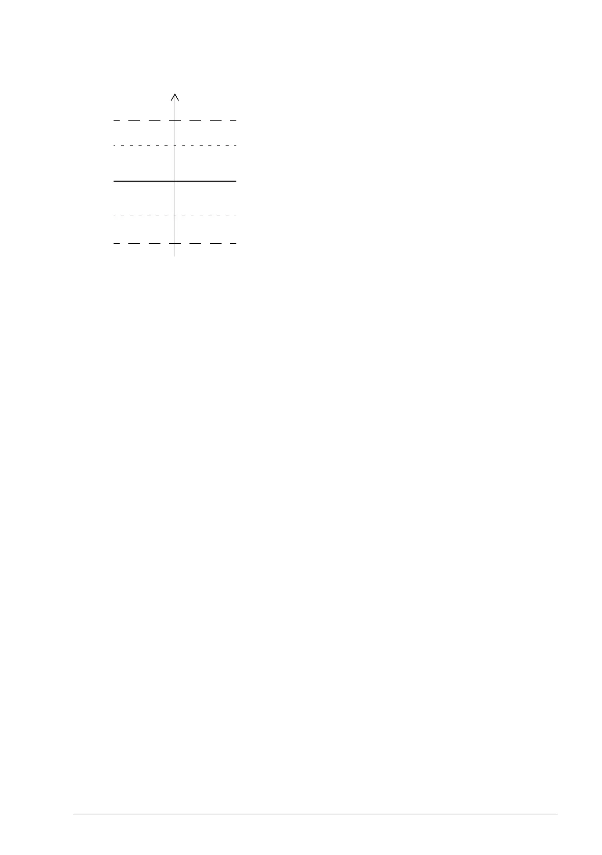
01.07 Dc-voltage
Undervoltage control level (0.8 × U
DC
; 400 V min.)
Undervoltage fault level (U
DC,
low - 50 V; 350 V min.)
Overvoltage control level (1.25 × U
DC
; 810 V max.)
Overvoltage fault level (U
DC,
high + 70 V; 880 V max.)*
U
DC
= 1.35 × 01.19 Used supply volt
U
DC
, high = 1.25 × U
DC
U
DC
, low = 0.8 × U
DC
*Drives with 230 V supply voltage (ACS850-04-xxxx-2): The overvoltage fault
level is set to 500 V.