Parameters and firmware blocks
154
(1) AI1 Analogue input AI1.
(2) AI2 Analogue input AI2.
(3) FBA REF1 Fieldbus reference 1.
(4) FBA REF2 Fieldbus reference 2.
(5) D2D REF1 Drive to drive reference 1.
(6) D2D REF2 Drive to drive reference 2.
32.02 TORQ REF ADD SEL FW block: TORQ REF SEL (see above)
Selects the source for the torque reference addition, 3.12 TORQUE REF ADD. Parameter 34.10
TORQ REF ADD SRC is connected to signal 3.12 TORQUE REF ADD by default.
Because the reference is added after the torque reference selection, this parameter can be used in
speed and torque control modes. See block diagram at parameter group 34 REFERENCE CTRL
(page 160).
(0) ZERO Zero reference addition.
(1) AI1 Analogue input AI1.
(2) AI2 Analogue input AI2.
(3) FBA REF1 Fieldbus reference 1.
(4) FBA REF2 Fieldbus reference 2.
(5) D2D REF1 Drive to drive reference 1.
(6) D2D REF2 Drive to drive reference 2.
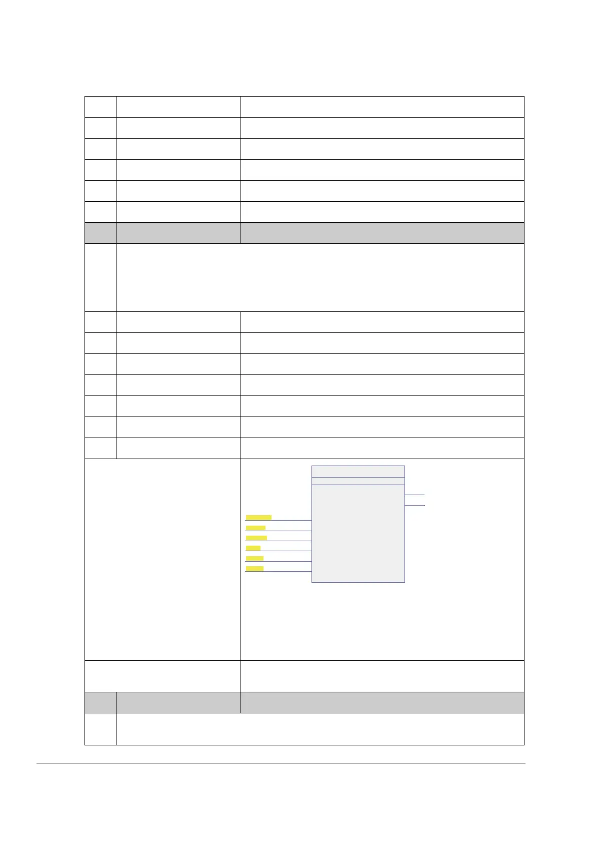
Firmware block:
TORQ REF MOD
(33)
This block
• selects the source for the torque
reference
• scales the input torque reference
according to the defined load share
factor
• defines limits for the torque
reference
• defines ramp-up and ramp-down
times for the torque reference
• shows the ramped torque reference
value and the torque reference
value limited by the rush control.
Block outputs located in other
parameter groups
3.10 TORQ REF RAMPED (page 87)
3.11 TORQ REF RUSHLIM (page 87)
32.03 TORQ REF IN FW block: TORQ REF MOD (see above)
Selects the source for the torque reference input for the torque ramp function. The default value is
P.3.9, i.e. signal 3.09 TORQ REF1, which is the output of the TORQ REF SEL firmware block.
TORQ REF MOD
2
TLF1 500 µsec (2)
< 32.03 TORQ REF IN
[ AI2 SCALED ]
(3 / 2.07)
32.04 MAXIMUM TORQ REF
[ 300.0 % ]
32.05 MINIMUM TORQ REF
[ -300.0 % ]
32.06 LOAD SHARE
[ 1.000 ]
32.07 TORQ RAMP UP
[ 0.000 s ]
32.08 TORQ RAMP DOWN
[ 0.000 s ]
3.10 TORQ REF RAMPED
3.11 TORQ REF RUSHLIM

 Loading...


