4.3.5 POINT DISPLAY 3 (CDM = 4, AUTO/MANUAL STATION)
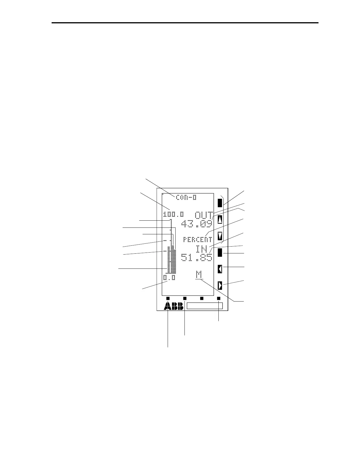
The Auto/Manual Station Display is illustrated in Figure 4-7. In the illustration the control module tag
name appears at the top of the display. The left side of the Auto/Manual Station Display (CDM = 4)
contains a fifty segment vertical axis with numerical values above and below it indicating its upper
and lower ranges. Left of the vertical axis is the alarmed variable indicator bar. Alarm limits appear
left of the alarmed variable indicator bar as indicators at the alarm limit values. On the immediate
right of the vertical axis is the auto-control signal bar. The station output bar appears adjacent to the
auto-control signal bar. On the right side of the display is the
OUT
put legend and the output value
appears immediately beneath it. The middle legend is the engineering units and the lower legend is
IN
put, with the auto-control signal value appearing below it. If the alarmed variable indicator bar
moves beyond either alarm limit indicator, an alarm overlay appears in the area below the control
module tag name. Three of the faceplate vertical keypad push buttons have no affect on the
Auto/Manual Station Display (R/L,
⇑
,and
⇓
push buttons are not applicable).
Figure 4-7. Point Display 3 (CDM = 4, Auto/Manual Station)
CONTROL MODULE TAG NAME
(A000)
CONTROLLER SPAN (C115) +
CONTROLLER LOWER RANGE
(C116)
50 SEGMENT VERTICAL AXIS
STATION OUTPUT BAR
AUTO-CONTROL SIGNAL BAR
ALARM LIMIT 1 (C103)*
ALARM LIMIT 2 (C104)*
ALARMED VARIABLE
INDICATOR BAR
CONTROLLER LOWER RANGE
(C116)
*(CONTROL ALARM MODE
B335 = 0)
**PB = PUSH BUTTON
MODE - ALARM RESET
F2 - PAGE IN LIST OR PAGE FORWARD
F1 - NEXT DISPLAY GROUP OR PAGE BACK
NOT APPLICABLE
OUTPUT LEGEND
OUTPUT VALUE
ENGINEERING UNITS
(A001)
AUTO-CONTROL INPUT
LEGEND
AUTO-CONTROL VALUE
A/M (AUTO/MANUAL)
SELECTOR PB**
M = DECREASE OUTPUT
PB
M = INCREASE OUTPUT
PB
M = MANUAL, A = AUTO
STATUS INDICATOR
Section 4. Operator Displays
4-19