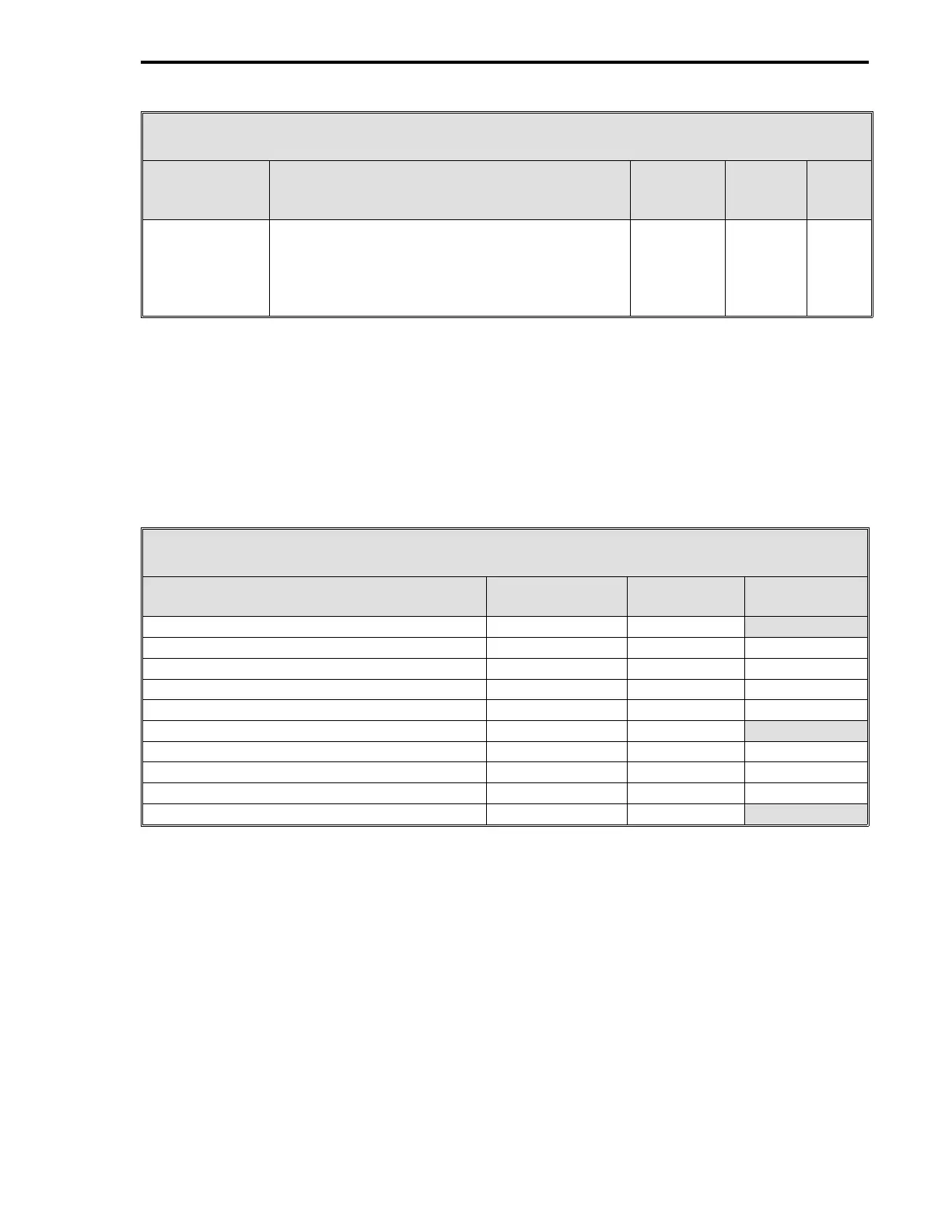
Table 14-1. CS40 Control Signals
Control
Signal Definition
Cord
Set
ITB
Rear
Term
Board
Signal
DO1 - #2
Secondary
Process
Alarms
This contact is closed when the #2 Secondary
Process Variable value is not within the C211
and C212 datapoint values (#2 Secondary
Alarm Limits 1 and 2); otherwise, the contact is
open.
TB2-7 (+)
TB2-8 (-)
18 (+)
17 (-)
DO1
PC
14.3 CS40 STANDARD DISPLAYS
Loading CS40 preconfigures the System Module display list for ten displays. The ten displays are
listed in Table 14-2 with appropriate reference sections, figure numbers, and configuration tables.
A configuration table is not listed for the Four Loop CON0 - CON3 display, as that information is
provided in this section. To configure the Horizontal Trend, System Status, and Status Module dis-
plays, reference the Section 4 and Section 5 information listed in the table. The Alarm Summary
display does not have to be configured; however, it is described and illustrated in Section 4.
Table 14-2. CS40 Standard Displays
Title
See
Section
Section 4
Figure
Section 5
Table
Four Loop CON0 - CON3 4.10 4-15
Single Loop CON0 with Horizontal Trend 4.5 4-10 sheet 2 5-9 and 5-12
Single Loop CON1 with Horizontal Trend 4.5 4-10 sheet 2 5-9 and 5-12
Single Loop CON2 with Horizontal Trend 4.5 4-10 sheet 2 5-9 and 5-12
Single Loop CON3 with Horizontal Trend 4.5 4-10 sheet 2 5-9 and 5-12
Alarm Summary 4.1 4-1
System Status 4.2 4-2 5-15
Status Module 0 4.7 4-12 5-10
Status Module 1 4.7 4-12 5-10
Four Loop CON0 - CON3 4.10 4-15
14.4 CS40 DATAPOINT CONFIGURATION SELECTIONS
See Figure 14-2 and Table 14-3 to configure datapoints for CS40 - Dual Two Loop Cascade Con-
troller. Table 14-3 also lists the Section 5 modules that can be referenced for more detailed defini-
tions of the datapoints when required.
A datapoint does not have to be configured if the
default value listed in Table 14-3 is appropriate for the process application.
Loading CS40 in-
itializes the Engineering Spans to 100 for AIs 1-3 (C257, C258, and C259). Also, C076 (Math A -
K1) is set to 1.0, C077 (Math A - K2) is set to -1.0, C085 (Math D - K1) is set to 1.0, and C086
(Math D - K2) is set to -1.0. The CON0
•
OUT and CON1
•
OUT signals, which are the secondary set-
point inputs, must be properly scaled by configuring datapoints C184 (B1) and C185 (K1) for the #1
Secondary Control Output; and by configuring C220 (B1) and C221 (K1) for the #2 Secondary Con-
trol Output. These datapoints are listed in Table 14-3 under their respective CON
•
OUT Datapoints.
2 of 2
Section 14. CS40 - Dual Two Loop Cascade Controller
14-3