Table 18-1. Parts Replacement
Step Procedure
Replacing a 53MC5000B Hi-Res Display with a Low-Res Display
12 Follow Steps 1-4 to remove the front display panel.
13 Follow Steps 30-33 to remove the Main PCB.
14
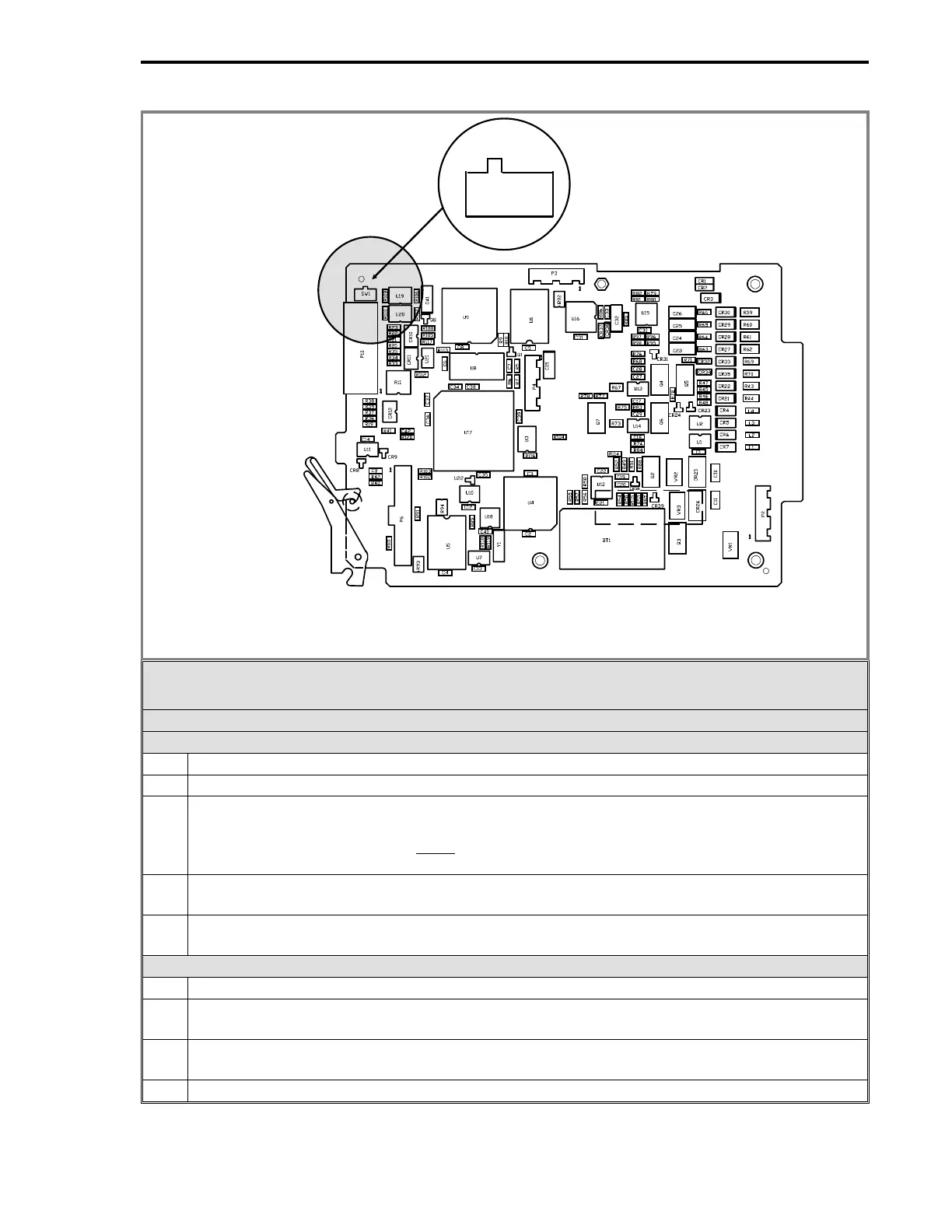
On the Main PCB, switch
SW1
(Refer to the figure above for
SW1
location) is used to apply
power to the Low Resolution Display continuously. When replacing a High Resolution with a
Low Resolution Display,
SW1
must
be placed in the
ON
position. The
ON
position requires
that power be removed from the controller before the display is removed or installed.
15
Remove the High Resolution display ribbon cable (614C157U02, 50 pin to 50 pin) and
replace it with the Low Resolution ribbon cable (614C157U01, 25 pin to 50 pin) .
16
Follow Steps 5 & 6 to install the new front display panel.
Expansion Board
17 Follow steps 1-4 to remove the front display panel.
18
Use the plastic front edge board ejector to pry the expansion board (item 7) free of its options
connector board (item 6) socket.
19
Carefully slide the expansion board forward to access the ribbon cable (item 9) socket
behind the option cards.
20 Disconnect the ribbon cable from J11 on the expansion board.
2 of 4
SW1 Location
MAIN PCB ASSEMBLY
SW1
OFF
ON
Section 18. Maintenance and Parts List
18-3