2.7.5 220/240 V AC (NO NEUTRAL) POWER SOURCE TO CONTROLLER
The procedure to connect the controller TB2 screw lugs to a 220 (208)/240 V ac (no neutral) power
source (208 V ac
±
10% variance) is provided in Table 2-7.
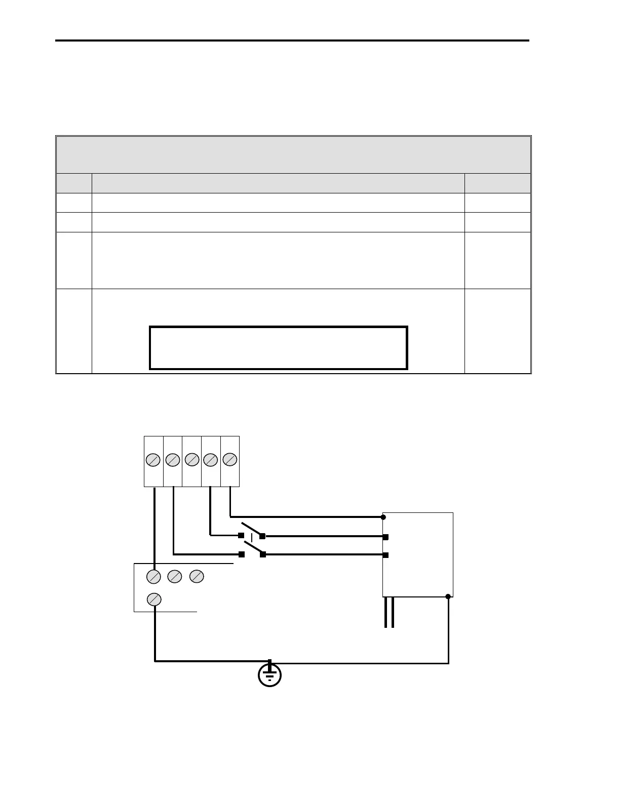
Table 2-7. 220/240 V ac (No Neutral) Power Source to Controller
Step Procedure See Figure
1 Connect the hot input line, via a remote DPST switch, to TB2-4 (
L1
). Figure 2-21
2 Connect the second hot input line, via a remote DPST switch to TB2-2 (
L3
). Figure 2-21
3 Connect TB2-1, Power Common (
PC
), to a bus bar that is connected to
earth ground.
Individual wires should connect each controller Power Common (
PC
) screw
lug to the common bus bar.
Figure 2-21
Figure 2-22
4 Connect the earth ground at the supply source (green/green-yellow ground)
to TB2-5, Chassis Safety Ground (
G
).
Figure 2-21
Note
SURGE PROTECTION
All supply connections include surge protection
rated at 275 V ac normal mode.
Figure 2-21. 220/240 V ac (No Neutral) Power Source to Controller
1 2 3 4 5
PC L3 L2 L1 G
DPST
HOT
EARTH GROUND
TB2 (REAR OF
CONTROLLER)
AC
BREAKER
220/240 V ac
BOX
HOT
HOT
HOT
COMMON BUS BAR FOR
ALL CONTROLLERS
53MC5000 Process Control Station
2-26