EasyManuals Logo
Home>ABB>Controller>ControlIT 53MC5000

ABB ControlIT 53MC5000 User Manual

ABB ControlIT 53MC5000
406 pages
To Next Page IconTo Next Page
To Previous Page IconTo Previous Page
Page #58 background imageLoading...
Page #58 background image
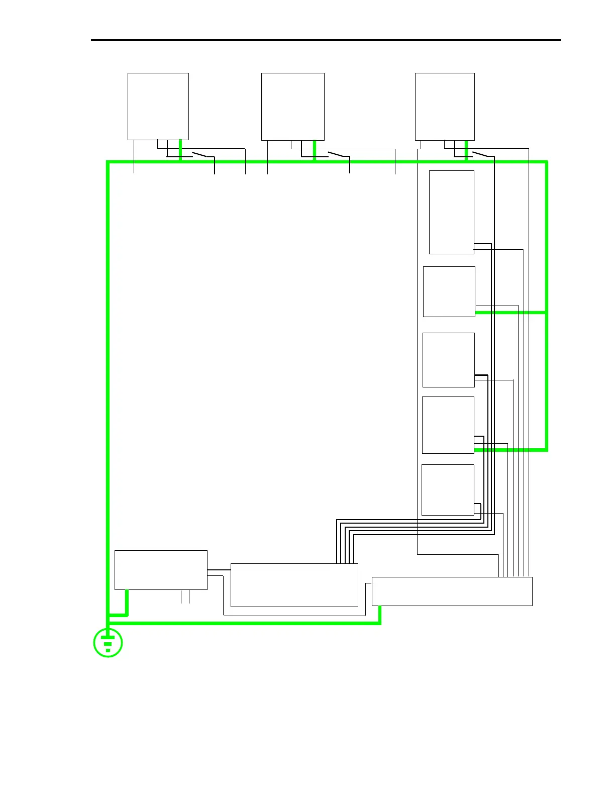
Figure 2-14. Wiring Example for Single+24 V dc Power Supply to
Controller and ITBs (Negative Ground System)
*DISTRIBUTION TERMINAL STRIP AND COMMON
BUS BAR NOT PROVIDED BY ABB Instrumentation.
**ASSUMES 24 V MODULES INSTALLED ON 16DI/DO.
*** P/S IS NEGATIVE GROUND.
SCADA
CORD
SET
ANALOG
16DI/DO**
24 V DC P/S***
24 V DC DISTRIBUTION
TERMINAL STRIP*
COMMON BUS BAR*
MC5000
1
MC5000
2
MC5000
3
DUAL
RELAY
+
-
AC
EARTH GROUND
PC L3 L2
L1 G
TB1
TB1
TB2
TB2
TB2
SPST
SPST
SPST
PC L3 L2
L1 G
PC L3 L2
L1 G
CONTROLLERS AND ITBs ARE WIRED SAME AS
CONTROLLER 3.
+24 V
9
10
1
2
1
2
1
2
Section 2. Installation
2-19

Table of Contents

Questions and Answers:

Question and Answer IconNeed help?

Do you have a question about the ABB ControlIT 53MC5000 and is the answer not in the manual?

ABB ControlIT 53MC5000 Specifications

General IconGeneral
BrandABB
ModelControlIT 53MC5000
CategoryController
LanguageEnglish

Related product manuals