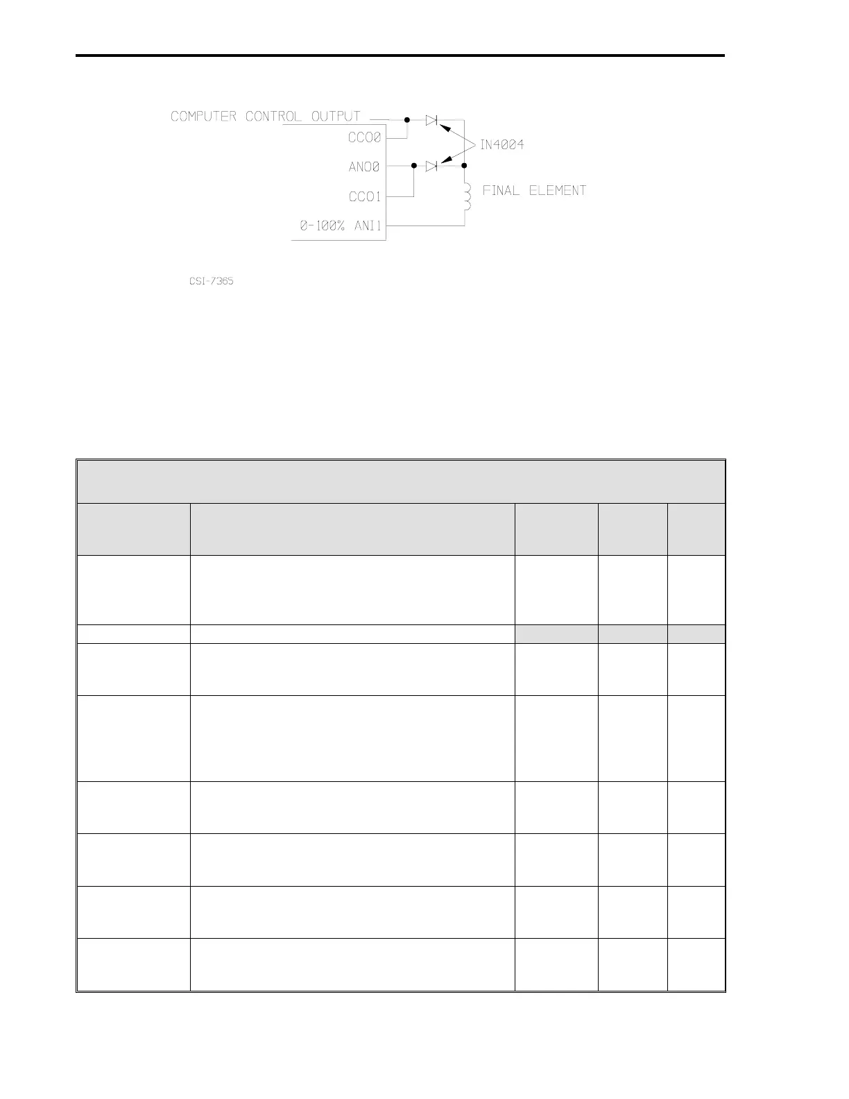
Figure 7-2. DO Output Diverter Circuit
7.2 CS2 CONTROL SIGNALS
Loading CS2 connects the 53MC5000 Controller function blocks for operation as an Analog
Backup Controller. As shown in Figure 7-1, up to nine control signals are available. Table 7-1 be-
low describes the nine signals in CS2.
Table 7-1. CS2 Control Signals
Control
Signal Definition
Cord
Set
ITB
Rear
Term
Board
Signal
AI0 - Process
Variable
This analog input signal represents the value of
the process to be manipulated by the controller.
It is compared to the control setpoint to
determine the Control Output value.
TB1-1 (+)
TB1-2 (-)
TB1-3
1 (+)
2 (-)
3
+24 V
AI0
SC
AI1 Not used.
AI2 - Additive
Feed Forward
Input
This analog input signal value is added to the
PID result to make up the Control Output value
when Auto operation is active.
TB1-9
TB1-10 (+)
TB1-11 (-)
1
7 (+)
8 (-)
+24 V
AI2
SC
AI3 - Control
Element
Feedback
A feedback signal from the diverter circuit to the
controller that indicates the position of the final
element (valve) so that if operation transfer to
the controller becomes necessary, it will be
bumpless.
TB1-13
TB1-14 (+)
TB1-15 (-)
4
9 (+)
8 (-)
+24 V
AI3
SC
AO0 - Backup
Control Output
This is the 4-20 mA output signal that drives the
final control element if operation is transferred
from the computer to the controller.
TB1-17 (+)
TB1-18 (-)
10 (+)
11 (-)
AO0
PC
AO1 -
Computer
Control Status
It indicates whether the computer (20 mA
output) or the controller (4 mA) is driving the
final element (valve).
TB1-19 (+)
TB1-20 (-)
12 (+)
11 (-)
AN01
PC
DI0 - Computer
Ready
It enables the computer to drive the final
element if it is a closed contact and if R is
selected with the faceplate R/L push button.
TB2-1 (+)
TB2-2 (-)
13 (+)
14 (-)
DI0
PC
DI1 - Auto
Enable
It enables the controller to drive the final
element if it is a closed contact and if L is
selected with the faceplate R/L push button.
TB2-3 (+)
TB2-4 (-)
15 (+)
14 (-)
DI1
PC
1 of 2
53MC5000 Process Control Station
7-2