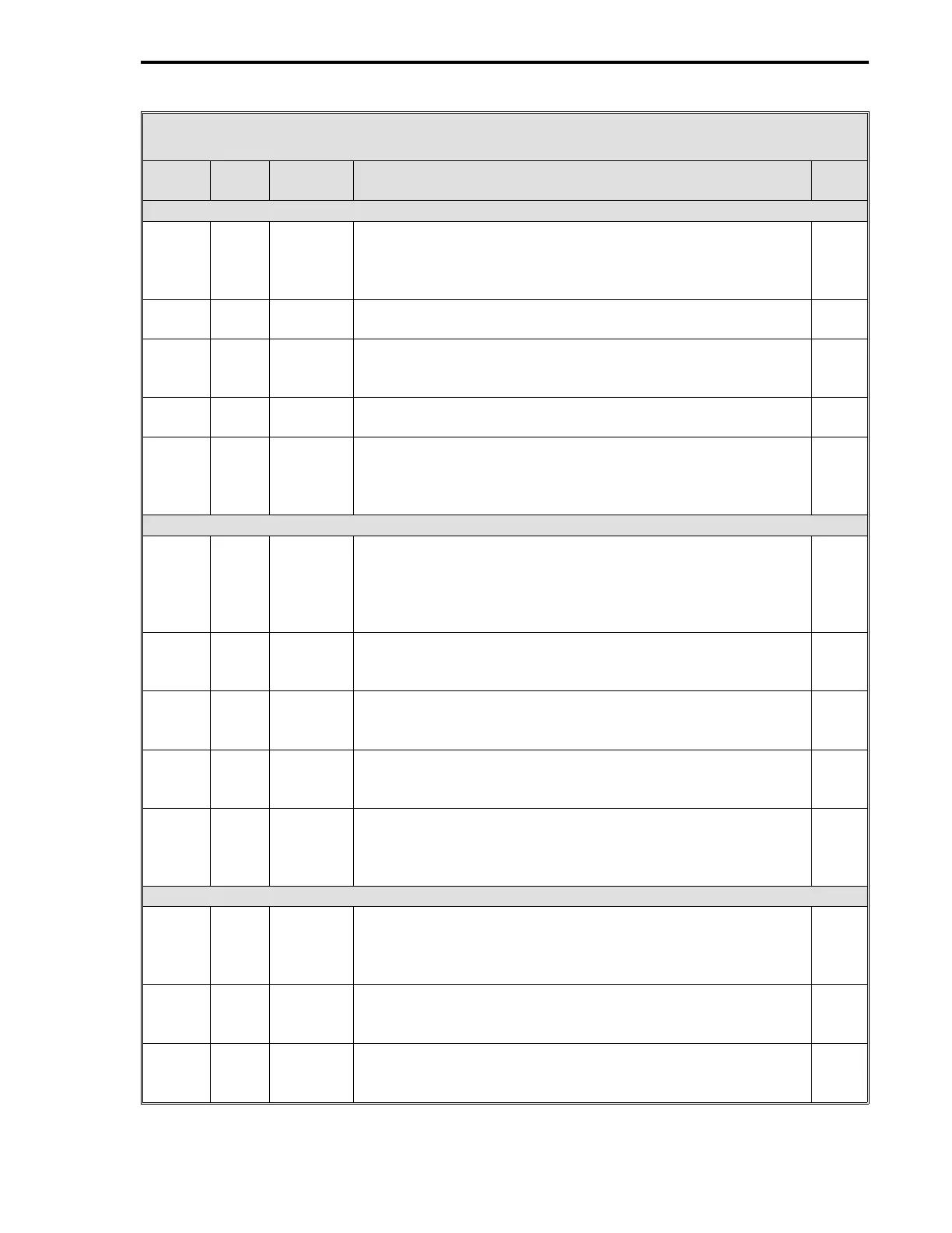
Table 10-3. CS5 Ratio Automatic/Manual Station Datapoints
Data-
point Table Module Title and Function
De-
fault
AI0 - Auto Input
C256 5-4 AI0 Engineering Span - Enter a value, that when added to the
Engineering Zero value, will produce an upper range value in
engineering units that represents the Auto Input upper range
signal value.
100
C276 5-4 AI0 Engineering Zero - Enter a value that represents in
engineering units the Auto Input lower range signal value.
0
B269 5-4 AI0 Digital Filter Index - This is a first order filter that can be
applied to the Auto Input signal. See Table 5-4 for input
values.
3
L416 5-4 AI0 0-5 V Input - Enter a value that matches the voltage range of
the Auto Input signal. 1 = 0 - 5 V range; 0 = 1 - 5 V range.
0
L440 5-4 AI0 Square Root Signal - It is used if the Auto Input signal is a
squared value. 0 = input is already linear; 1 = square root to
restore linearization.
0
AI1 - Remote Ratio Input
C257 5-4 AI1 AI1 Engineering Span - Set to 100 by CS5; however, it can
be changed. Enter a value, that when added to the
Engineering Zero value, will produce an upper range value in
engineering units that represents the Remote Ratio Input
upper range signal value.
0
C277 5-4 AI1 Engineering Zero - Enter a value that represents in
engineering units the Remote Ratio Input lower range signal
value.
0
B270 5-4 AI1 Digital Filter Index - This is a first order filter that can be
applied to the Remote Ratio Input signal. See Table 5-4 for
input values.
3
L417 5-4 AI1 0-5 V Input - Enter a value that matches the signal voltage
range of the Remote Ratio Input signal. 1 = 0 - 5 V input
range; 0 = 1 - 5 V input range.
0
L441 5-4 AI1 Square Root Signal - It is used if the Remote Ratio input is a
squared signal value that must be linearized. 0 = input is
already linear; 1 = square root to restore linearization.
0
AI2 - Alarmed Variable
C258 5-4 AI2 Engineering Span - Enter a value, that when added to
Engineering Zero, will produce an upper range value in
engineering units that represents the Alarmed Variable upper
range signal value.
0
C278 5-4 AI2 Engineering Zero - Enter a value that represents in
engineering units the Alarmed Variable lower range signal
value.
0
B271 5-4 AI2 Digital Filter Index - This is a first order filter that can be
applied to the Alarmed Variable signal. See Table 5-4 for
input values.
3
1 of 3
Section 10. CS5 - Ratio Automatic/Manual Station
10-5