11.0 CS20 - TWO LOOP CONTROLLER
11.1 CS20 - TWO LOOP CONTROLLER
A two loop 53MC5000 Controller is configured at the factory for CS20 operation to provide the
standard displays listed in Table 11-2 and the default datapoint settings listed in Table 11-3. As a
Two Loop (PID) Controller, each loop Proportional Band is set at 100%; the Process Variables AI0-
1 are scaled 0-100% for linear 4-20 mA input signals; and AO0-1 are set as reverse action (PV
above setpoint causes decreasing value) control signals over a 4-20 mA signalling range. These
settings may be altered and additional Control Strategy 20 (CS20) functions can be activated as ne-
cessitated by the process application. The Two Loop Controller provides two identical standard
PID controllers with both control loops fully independent of each other. The input/output signals for
the two control loops are identical: Process Variable (PV), Remote Setpoint, Remote Setpoint En-
able, Control Output, and Process Alarms.
Just as with the standard Single Loop (PID) Controller,
only the Process Variable and Control Output of each loop are required for control purposes; the
other signals do not have to be connected or configured
. Each loop calculates an output from the
difference between its Process Variable feedback signal sent from a Field Transmitter (FT) (e.g,
flow meter) and its setpoint (SP) value. After the output is calculated, it is applied to a final control
loop element (e.g, valve) to restore process flow to the loop setpoint value.
Validate the controller
model number to ensure it has the necessary two loop hardware capabilities.
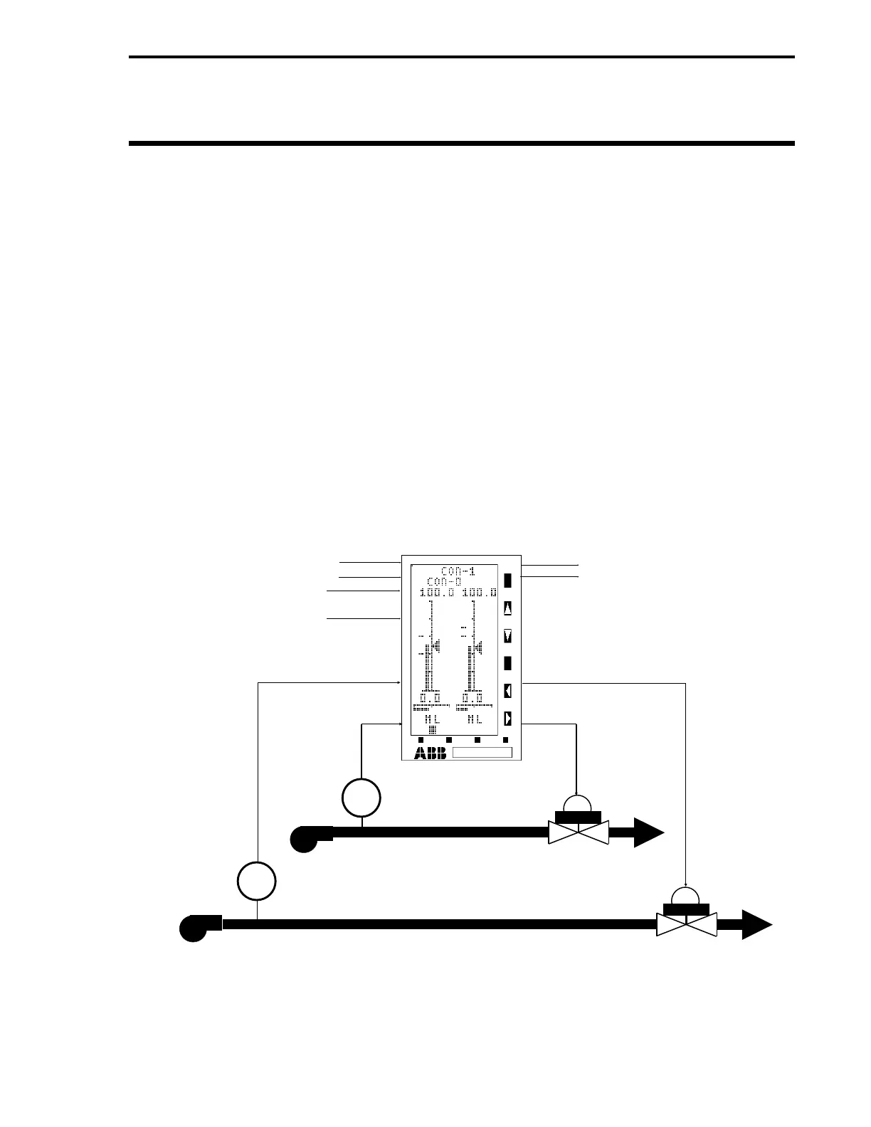
A typical low-resolu-
tion display Two Loop Controller process application is illustrated in Figure 11-1.
Figure 11-1. Typical CS20 Two Loop Controller Application
PUMP
VALVE
LOOP 1
PUMP
VALVE
LOOP 2
FT
AI2 - REMOTE SETPOINT LOOP 1
AI3 - REMOTE SETPOINT LOOP 2
DI0 - REMOTE ENABLE LOOP 1
(CLOSED CONTACT)
DI1 - REMOTE ENABLE LOOP 2
(CLOSED CONTACT)
AI1 - PROCESS
VARIABLE LOOP 2
AI0 - PROCESS
VARIABLE LOOP 1
DO0 - PROCESS ALARMS LOOP 1
DO1 - PROCESS ALARMS LOOP 2
AO1 - CONTROL
OUTPUT LOOP 2
AO0 - CONTROL
OUTPUT LOOP 1
FT
Section 11. CS20 - Two Loop Controller
11-1