5.4 ANALOG INPUT MODULES (AI0-8)
The Analog Input Modules (AI0-8) are used to configure the characteristics of each input. Inputs AI4 through AI8 are active only if the ap-
propriate hardware option is installed. The nine Analog Input Modules are listed in Table 5-4. Each module can be configured sepa-
rately.
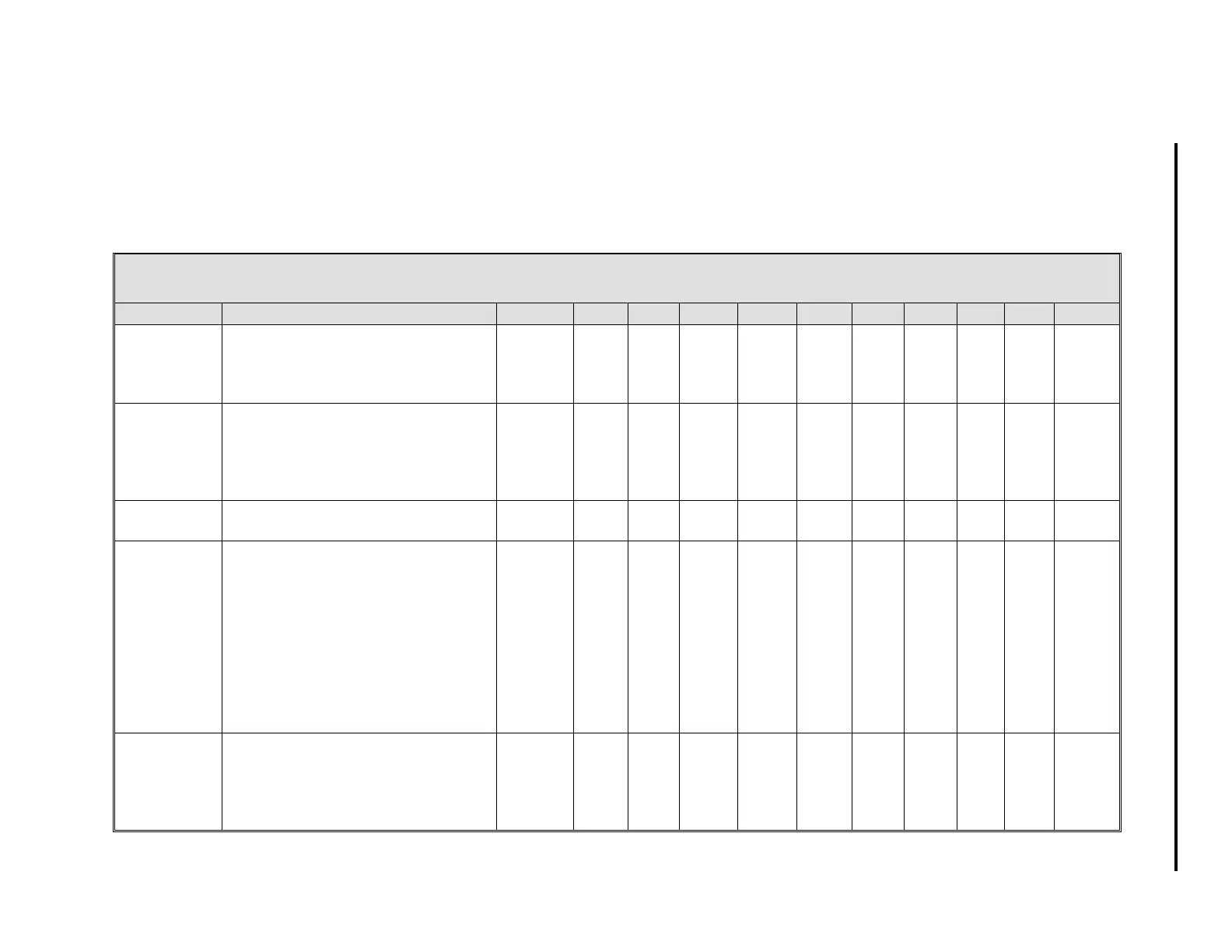
Table 5-4. Analog Input Modules (AI0-8)
Title Definition Atom AI0 AI1 AI2 AI3 AI4 AI5 AI6 AI7 AI8 Default
Analog Input This is the value in engineering
units of the measured input after all
signal conditioning has been
applied.
AI
(0-8)
H000 H001 H002 H003 H004 H005 H006 H007 H008 0
Engineering
Span
This value determines the upper
range the analog input represents
in engineering units. The upper
range value equals Engineering
Zero plus Engineering Span.
SPAN
(0-8)
C256 C257 C258 C259 C260 C261 C262 C263 C264 100/0
Engineering
Zero
This is the lower range value. ZERO
(0-8)
C276 C277 C278 C279 C280 C281 C282 C283 C284 0
Digital Filter
Index
This entry controls a first order filter
that is applied to the input signal.
The time constant is entered as an
index value as follows:
0
- None (no effect),
1
- 0.05 s
6
- 3.1 s
11
- 102 s
2
- 0.1 s
7
- 6.3 s
12
- 205 s
3
- 0.3 s
8
- 12.7 s
13
- 410 s
4
- 0.7 s
9
- 25.5 s
14
- 819 s
5
- 1.5 s
10
- 51.1 s
15
- 1638 s
DFILT
(0-8)
B269 B270 B271 B272 B273 B274 B275 B276 B277 3
Signal Base This value specifies the signaling
range of the input.
0
- 4-20 mA (1 - 5V)
1
- 0-20 mA (0 - 5V)
BASE
(0-8)
L416 L417 L418 L419 L420 L421 L422 L423 L424 0
1 of 3
5-5
Section 5. Configuration Parameters