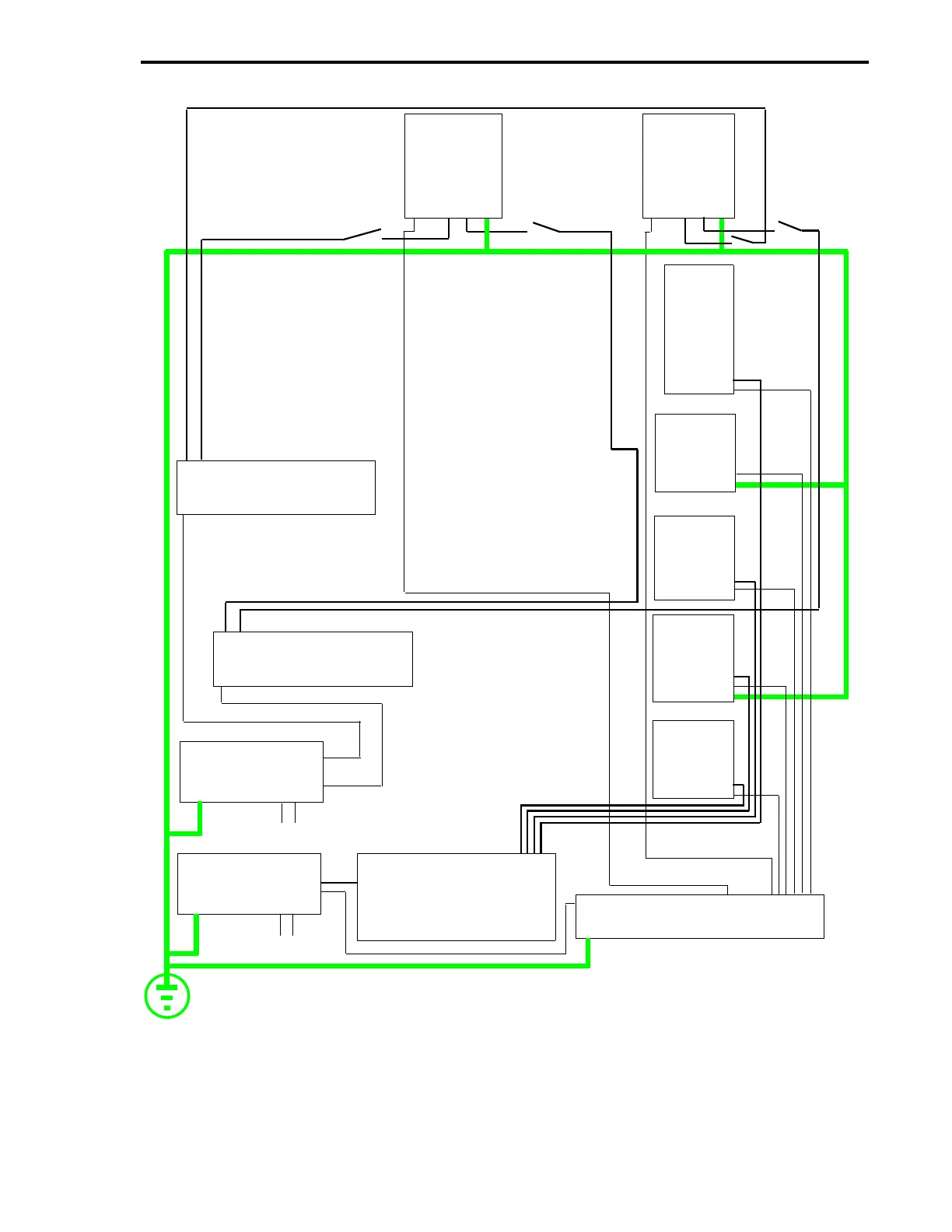
Figure 2-16. Wiring Example of Separate 24 V dc Power Sources for
Controller and ITBs (Controller Positive, Negative, or Floating Ground)
ONLY ONE SPST
SWITCH PER
CONTROLLER IS
NEEDED. (SEE TABLE
2-4.) THE
CONTROLLER P/S CAN
BE TO A POSITIVE
GROUND, NEGATIVE
GROUND, OR FLOAT.
SCADA
CORD
SET
ANALOG
16DI/DO**
ITB
24 V DC P/S***
ITB 24 V DC
DISTRIBUTION
TERMINAL STRIP*
COMMON BUS BAR*
MC5000
1
MC5000
2
DUAL
RELAY
+
-
AC
EARTH GROUND
TB1
TB1
TB2
TB2
TB2
SPST
SPST
PC L3 L2
L1 G
PC L3 L2
L1 G
CONTROLLER
24 V DC P/S
NEGATIVE
TERMINAL STRIP*
-
+
NOTE:
THE POWER
SUPPLY
DEDICATED TO
THE ITBs MUST
STILL BE
CONNECTED TO A
NEGATIVE
GROUND.
AC
POSITIVE
TERMINAL STRIP*
SPST
ITBs ARE WIRED
SAME AS THOSE
UNDER
CONTROLLER 2.
*TERMINAL STRIPS AND COMMON BUS BAR NOT
PROVIDED BY ABB AUTOMATION.
**ASSUMES 24 V MODULES INSTALLED ON 16DI/DO.
*** P/S IS NEGATIVE GROUND.
1
2
1
2
1
2
+24 V
9
10
Section 2. Installation
2-21