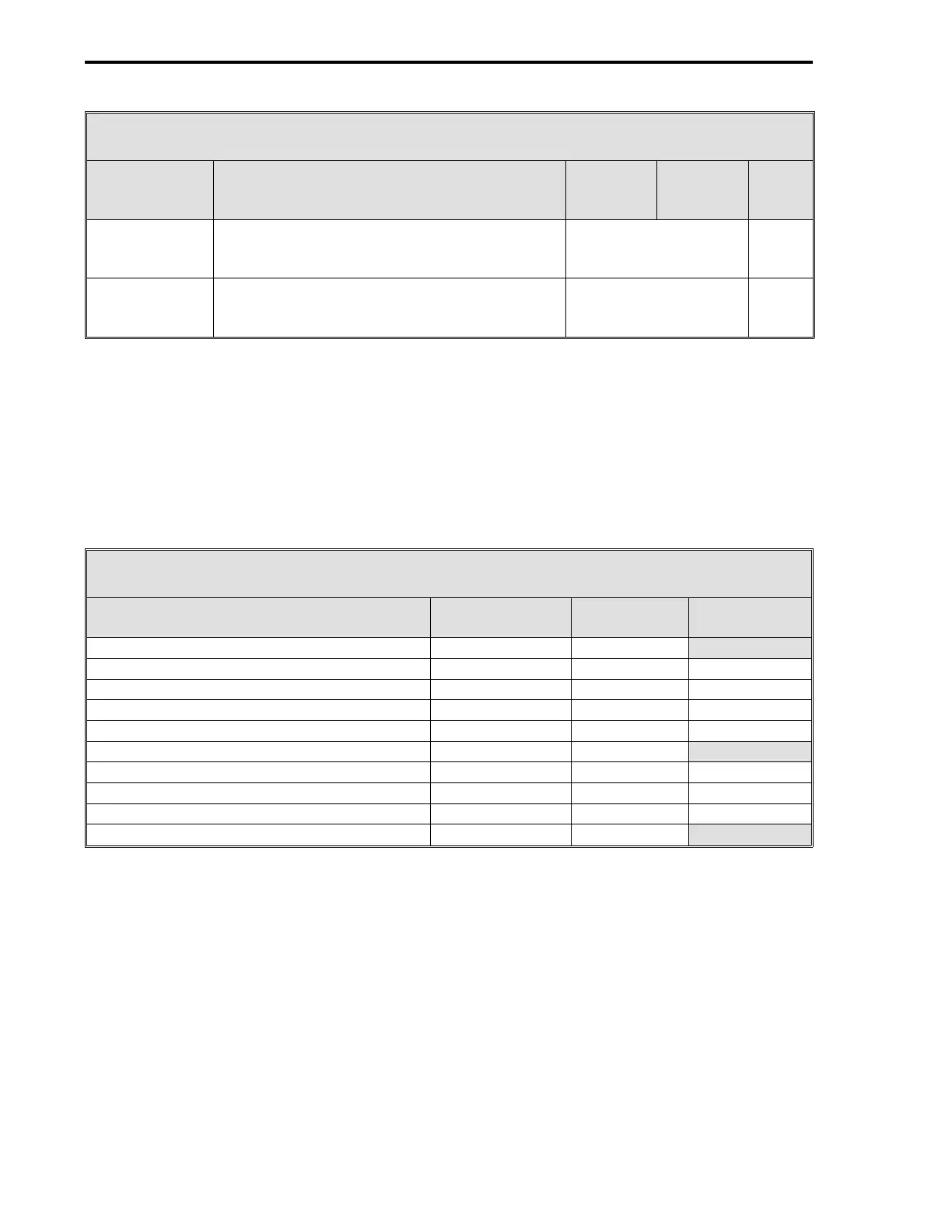
Table 15-1. CS41 Control Signals
Control
Signal Definition
Cord
Set
ITB
Rear
Term
Board
Signal
CCO2 -
Process Alarms
Loop 3
This contact is closed when the Loop 3 PV
value is not within Alarm Limits 1 and 2 (C175
and C176); otherwise, the contact is open.
6DI/4DO
ITB
TB2
TB2-1 (+)
TB2-2 (-)
CCO2+
CC02-
CCO3 -
Process Alarms
Loop 4
This contact is closed when the Loop 4 PV
value is not within Alarm Limits 1 and 2 (C211
and C212); otherwise, the contact is open.
6DI/4DO
ITB
TB2
TB2-3 (+)
TB2-4 (-)
CCO3+
CC03-
15.3 CS41 STANDARD DISPLAYS
Loading CS41 preconfigures the System Module display list for ten displays. The ten displays are
listed in Table 15-2 with appropriate reference sections, figure numbers, and configuration tables.
A configuration table is not listed for the Four Loop CON0 - CON3 display, as that information is
provided in this section. To configure the Horizontal Trend, System Status, and Status Module dis-
plays, reference the Section 4 and Section 5 information listed in the table. The Alarm Summary
display does not have to be configured; however, it is described and illustrated in Section 4.
Table 15-2. CS41 Standard Displays
Title
See
Section
Section 4
Figure
Section 5
Table
Four Loop CON0 - CON3 4.10 4-15
Single Loop CON0 with Horizontal Trend 4.5 4-10 sheet 2 5-9 and 5-12
Single Loop CON1 with Horizontal Trend 4.5 4-10 sheet 2 5-9 and 5-12
Single Loop CON2 with Horizontal Trend 4.5 4-10 sheet 2 5-9 and 5-12
Single Loop CON3 with Horizontal Trend 4.5 4-10 sheet 2 5-9 and 5-12
Alarm Summary 4.1 4-1
System Status 4.2 4-2 5-15
Status Module 0 4.7 4-12 5-10
Status Module 1 4.7 4-12 5-10
Four Loop CON0 - CON3 4.10 4-15
15.4 CS41 DATAPOINT CONFIGURATION SELECTIONS
See Figure 15-2 and Table 15-3 to configure datapoints for CS41 - Four Loop Controller.
Table 15-3 also lists the Section 5 modules that can be referenced for more detailed definitions of
the datapoints when required.
A datapoint does not have to be configured if the default value
listed in Table 15-3 is appropriate for the process application.
Loading CS41 initializes the En-
gineering Spans AI1-7 to 100 (C257 - C263). When an open contact is present on CCI4, CCI5,
CCI6, or CCI7 (Force Fallback Loops 1-4), the loop’s output and setpoint are forced to fallback val-
ues contained in the CON0-3 modules Output Track Value (OTV) and Setpoint Track Value (STV)
datapoints (OTV = C129, C165, C201, and C237; STV = C128, C164, C200, and C236) only if the
CON0-3 modules Output Track Enable (OTE) and Setpoint Track Enable (STE) datapoints are con-
figured to 1 (OTE = L119, L143, L167, and L191; STE = L118, L142, L166, and L190).
3 of 3
53MC5000 Process Control Station
15-4