15.0 CS41 - FOUR LOOP CONTROLLER
15.1 CS41 - FOUR LOOP CONTROLLER
A four loop 53MC5000 Controller is configured at the factory for CS41 operation to provide the
standard displays listed in Table 15-2 and the default datapoint settings listed in Table 15-3. As a
Four Loop (PID) Controller, each loop Proportional Band is set at 100%; the Process Variables AI0-
7 are scaled 0-100% for linear 4-20 mA input signals; and AO0-1 are set as reverse action (PV
above setpoint causes decreasing value) control signals over a 4-20 mA signalling range. These
settings may be altered and additional Control Strategy 41 (CS41) functions can be activated as ne-
cessitated by the process application. The Four Loop Controller provides four identical standard
PID controllers. All four sets of input/output signals for the control loops are identical: Process Vari-
able (PV), Remote Setpoint, Remote Setpoint Enable, Force Fallback, Control Output, and Process
Alarms.
Just as with the standard Single Loop (PID) Controller, only the Process Variable and Con-
trol Output of each loop are required for control purposes; the other signals do not have to be con-
nected or configured.
Each loop calculates an output from the difference between its Process
Variable feedback signal and its setpoint (SP) value. After the output is calculated, it is applied to
a final control loop element (e.g, valve) to restore process flow to the loop setpoint value.
Validate
the controller model number to ensure it has the necessary four loop hardware capabilities
. A typi-
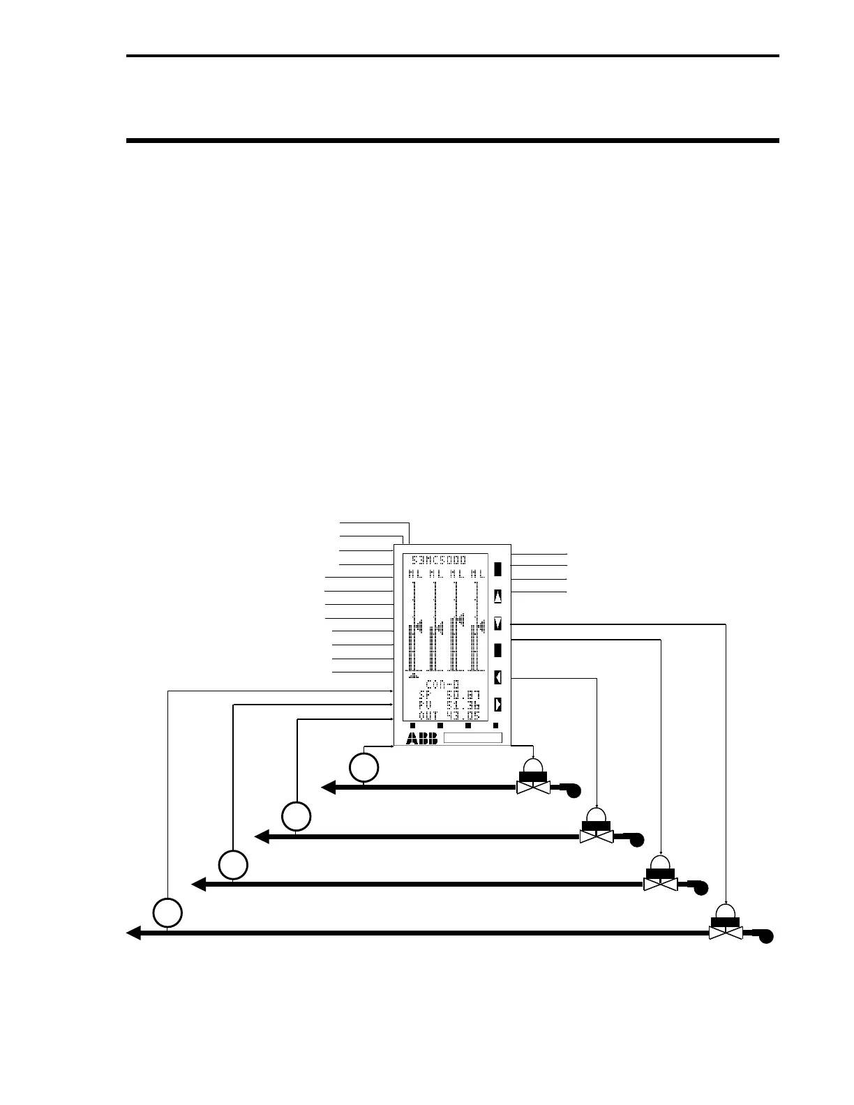
cal low-resolution display Four Loop Controller process application is illustrated in Figure 15-1.
Figure 15-1. Typical CS41 Four Loop Controller Application
LOOP 1
LOOP 2
LOOP 3
LOOP 4
CCI0 - REMOTE SP ENABLE LOOP 1
CCI1 - REMOTE SP ENABLE LOOP 2
CCI2 - REMOTE SP ENABLE LOOP 3
CCI3 - REMOTE SP ENABLE LOOP 4
CCI4 - FORCE FALLBACK LOOP 1
CCI5 - FORCE FALLBACK LOOP 2
CCI6 - FORCE FALLBACK LOOP 3
CCI7 - FORCE FALLBACK LOOP 4
AI2 - REMOTE SETPOINT LOOP 1
AI3 - REMOTE SETPOINT LOOP 2
AI6 - REMOTE SETPOINT LOOP 3
AI7 - REMOTE SETPOINT LOOP 4
AI5 - PV LOOP 4
AI4 - PV LOOP 3
AI1 - PV LOOP 2
AI0 - PV
LOOP 1
CCO0 - PROCESS ALARMS LOOP 1
CCO1 - PROCESS ALARMS LOOP 2
CCO2 - PROCESS ALARMS LOOP 3
CCO3 - PROCESS ALARMS LOOP 4
AO3 - CONTROL OUTPUT LOOP 4
AO2 - CONTROL OUTPUT LOOP 3
AO1 - CONTROL
OUTPUT LOOP 2
AO0 -
CONTROL
OUTPUT
LOOP 1
VALVE
FT
VALVE
VALVE
VALVE
FT
FT
FT
Section 15. CS41 - Four Loop Controller
15-1