2.7.1 SINGLE +24 V DC POWER SOURCE TO CONTROLLER AND ITBS
The procedure to connect the controller TB2 screw lugs to a +24 V dc power source is provided in
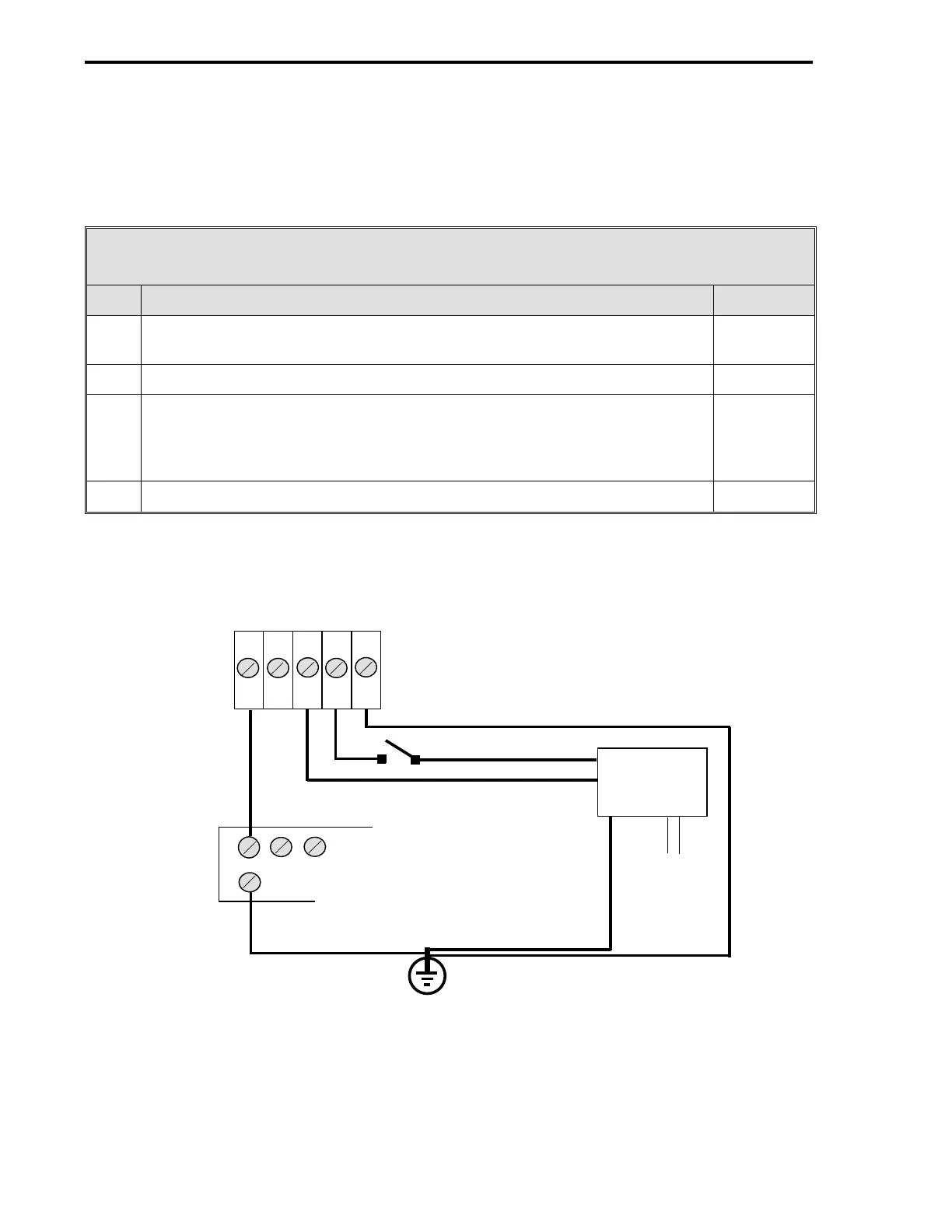
Table 2-3. This procedure assumes the power supply, controller, and ITBs are negatively
grounded (negative ground system).
Table 2-3. Single +24 V dc Power Source to Controller and ITBs
Step Procedure See Figure
1 Connect the positive (+) 24 V input line, via a remote SPST switch, to TB2-4
(
L1
).
Figure 2-13
2 Connect the negative (-) 24 V input line to TB2-3 (
L2
). Figure 2-13
3 Connect TB2-1, Power Common (
PC
), to a bus bar that is connected to
earth ground.
Individual wires should connect each controller Power Common (
PC
) screw
lug to the common bus bar.
Figure 2-13
Figure 2-14
4 Connect the earth ground to TB2-5, Chassis Safety Ground (
G
). Figure 2-13
Figure 2-13. Single +24 V dc Power Source to Controller and ITBs
1 2 3 4 5
PC L3 L2 L1 G
SPST
24 V dc
POWER
SUPPLY
-
+
EARTH GROUND
TB2 (REAR OF
CONTROLLER)
AC
COMMON BUS BAR FOR
ALL CONTROLLERS
53MC5000 Process Control Station
2-18