9.2 CS4 CONTROL SIGNALS
Loading CS4 connects the 53MC5000 Controller function blocks for operation as an Automatic/
Manual Station. As shown in Figure 9-1, CS4 provides eight control signals which are described in
Table 9-1:
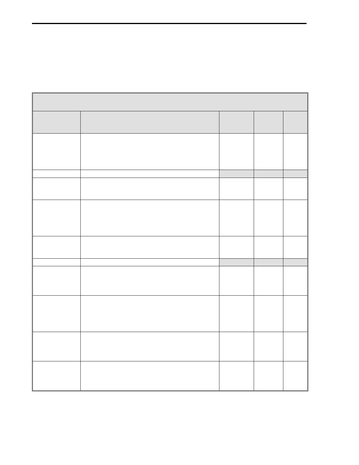
Table 9-1. CS4 Control Signals
Control
Signal Definition
Cord
Set
ITB
Rear
Term
Board
Signal
AI0 - Auto
Input
This analog signal is gated through as the AO0
Station Output if DI0 and DI1 are both closed
(DI0 closed = no Output Tracking and DI1
closed = Enable Auto). Also, A (Auto) must be
selected with the A/M faceplate push button.
TB1-1 (+)
TB1-2 (-)
TB1-3
1 (+)
2 (-)
3
+24 V
AI0
SC
AI1 Not used.
AI2 - Alarmed
Variable
It is the designated input variable that is
checked to be within acceptable process limits.
TB1-9
TB1-10 (+)
TB1-11 (-)
1
7 (+)
8 (-)
+24 V
AI2
SC
AI3 - Tracking
Input
This analog input signal value becomes the
Station Output value when the Force Output
Tracking contact input is open and datapoint
L119 (Enable Output Tracking) is configured to a
1.
TB1-13
TB1-14 (+)
TB1-15 (-)
4
9 (+)
8 (-)
+24 V
AI3
SC
AO0 -
Station
Output
It is the selected analog 4-20 mA output signal
that is sent to the final control element.
TB1-17 (+)
TB1-18 (-)
10 (+)
11 (-)
AO0
PC
AO1 Not used.
DI0 - Force
Output
Tracking
When an open contact is present on this input,
the Station Output value is forced to match the
Tracking Input value when datapoint L119
(Enable Output Tracking) is configured to a 1.
TB2-1 (+)
TB2-2 (-)
13 (+)
14 (-)
DI0
PC
DI1 - Auto
Enable
When a closed contact is present on this input
and Auto is selected with the A/M faceplate push
button, it enables the Auto Input analog signal
value on AI0 to be selected as the AO0 Station
Output.
TB2-3 (+)
TB2-4 (-)
15 (+)
14 (-)
DI1
PC
DO0 - Process
Alarm 1
This contact is closed when the Alarmed
Variable value is not within the C103 value
setting (Alarm Limit 1 datapoint); otherwise, the
contact is open.
TB2-5 (+)
TB2-6 (-)
16 (+)
17 (-)
DO0
PC
DO1 - Process
Alarm 2
This contact is closed when the Alarmed
Variable value is not within the C104 value
setting (Alarm Limit 2 datapoint); otherwise, the
contact is open.
TB2-7 (+)
TB2-8 (-)
18 (+)
17 (-)
DO1
PC
53MC5000 Process Control Station
9-2