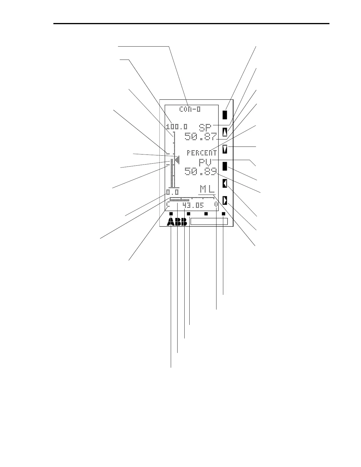
Figure 4-3. Point Displays 3, 4, 5, and 6 (CDM = 0, Standard PID)
(Sheet 1 of 5)
CONTROL MODULE
TAG NAME (A000)
CONTROLLER SPAN
(C115) + CONTROLLER
LOWER RANGE (C116)
50 SEGMENT VERTICAL
AXIS
HIGH ALARM LIMIT
INDICATOR - CON0
ALARM LIMIT 1 (C103)
(ALSO CONTROL
ALARM MODE, B335 = 0)
SETPOINT ARROWHEAD
PROCESS VARIABLE
BAR
LOW ALARM LIMIT
INDICATOR - CON0
ALARM LIMIT 2 (C104)
CONTROLLER LOWER
RANGE (C116)
40 SEGMENT
HORIZONTAL AXIS
C = CLOSE VALVE (SEE
REVERSE VALVE L109)
MODE - ALARM RESET
O = OPEN VALVE
F2 - PAGE IN LIST OR PAGE FORWARD
OUTPUT VALUE
OUTPUT BAR
F1 - NEXT DISPLAY GROUP OR PAGE BACK
R/L - REMOTE/LOCAL
SETPOINT CONTROL
PB
SP = SETPOINT
LEGEND
L = SETPOINT UP
ARROW PB*
SETPOINT DIGITAL
VALUE
ENGINEERING UNITS
(A001)
L = SETPOINT DOWN
ARROW PB
PROCESS VARIABLE
AUTO/MANUAL OUTPUT
SELECTOR PB
PROCESS VARIABLE
VALUE
M = DECREASE OUT-
PUT PB
M = INCREASE OUTPUT
PB
M = MANUAL, L = LOCAL
STATUS INDICATORS
CON0 CONFIGURED WITH HIGH
ANDLOW ALARM LIMITS.
*PB = PUSH BUTTON IN
ILLUSTRATION.
Section 4. Operator Displays
4-11