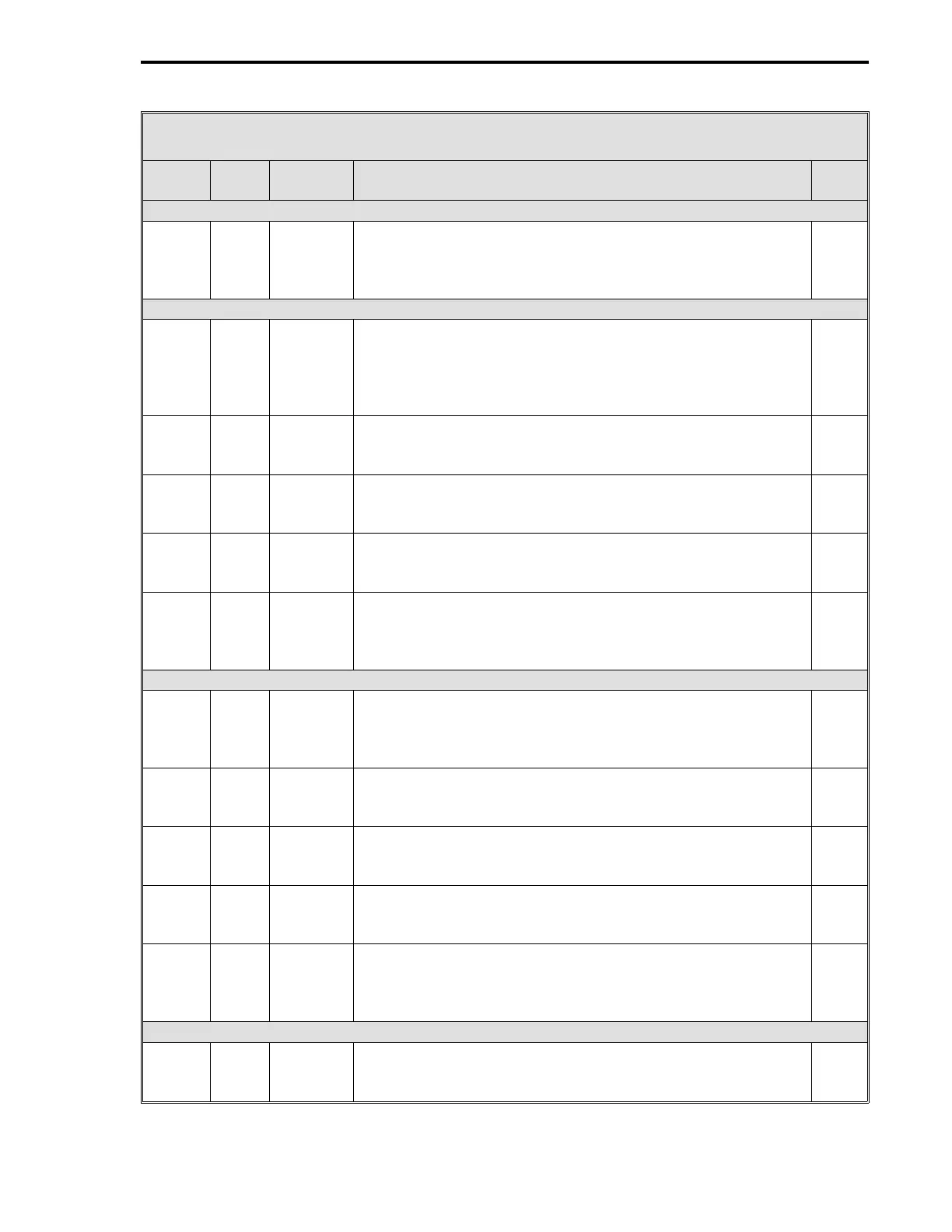
Table 12-3. CS21 Two Loop Cascade Controller Datapoints
Data-
point Table Module Title and Function
De-
fault
AI1 - Remote Setpoint Primary (Is affected by Setpoint Related Datapoints) (Cont)
L441 5-4 AI1 Square Root Signal - It is used if the Primary Remote
Setpoint is a squared signal value that must be linearized. 0
= input is already linear; 1 = square root to restore
linearization.
0
AI2 - Process Variable Secondary
C258 5-4 AI2 Engineering Span - Set to 100 by CS21; however, it can be
changed. Enter a value, that when added to the Engineering
Zero value, will produce an upper range value in engineering
units that represents the Secondary PV transducer upper
range signal value.
0
C278 5-4 AI2 Engineering Zero - Enter a value that represents in
engineering units the Secondary PV transducer lower range
signal value.
0
B271 5-4 AI2 Digital Filter Index - This is a first order filter that can be
applied to the Secondary PV signal. See Table 5-4 for input
values.
3
L418 5-4 AI2 0-5 V Input - Enter a value that matches the signal voltage
range of the Secondary PV signal. 1 = 0 - 5 V input range; 0
= 1 - 5 V input range.
0
L442 5-4 AI2 Square Root Signal - It is used if the Secondary PV input is a
squared signal value that must be linearized. 0 = input is
already linear; 1 = square root to restore linearization.
0
AI3 - Additive Feed Forward Secondary
C259 5-4 AI3 Engineering Span - Enter a value, that when added to
Engineering Zero, will produce an upper range value in
engineering units that represents the Additive Feed Forward
upper range signal value.
0
C279 5-4 AI3 Engineering Zero - Enter a value that represents in
engineering units the Additive Feed Forward lower range
signal value.
0
B272 5-4 AI3 Digital Filter Index - This is a first order filter that can be
applied to the Additive Feed Forward signal. See Table 5-4
for input values.
3
L419 5-4 AI3 0-5 V Input - Enter a value that matches the signal voltage
range of the Additive Feed Forward signal. 1 = 0 - 5 V input
range; 0 = 1 - 5 V input range.
0
L443 5-4 AI3 Square Root Signal - It is used if the Additive Feed Forward
input is a squared signal value that must be linearized. 0 =
input is already linear; 1 = square root to restore linearization.
0
AO0 - Control Output (Secondary)
L472 5-5 AO0 0-20 mA Output - 0 = 4-20 mA signal; 1 = 0-20 mA signal.
Enter a value to match the Secondary Control Output valve
requirements.
0
2 of 6
Section 12. CS21 - Two Loop Cascade Controller
12-7