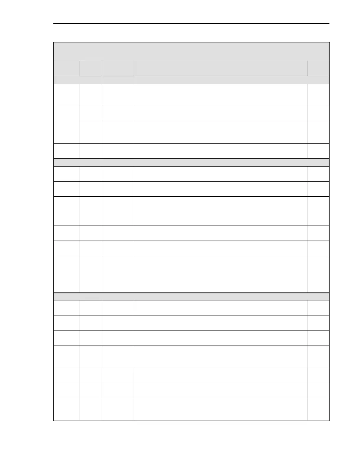
Table 14-3. CS40 Dual Two Loop Cascade Controller Datapoints
Data-
point Table Module Title and Function
De-
fault
CON1
•
OUT (Setpoint from Loop 2 to Loop 4) (Cont)
C147 5-9 CON1 Manual Reset - It determines output valve position when the
controller Loop 2 is in Auto and the error = 0. It is mutually
exclusive with Reset Time.
50
L138 5-9 CON1 Auto Enable - Output is from the PID algorithm when set to 1
and the A/M push button is in Auto.
1
C115 5-9 CON1 Controller Span - Enter a value, that when added to the
Loop 2 Control Lower Range value, will produce the Control
upper range value in engineering units.
100
C152 5-9 CON1 Controller Lower Range - Enter a value that represents in
engineering units the Loop 2 Control lower range value.
0
AO1 - #2 Secondary Control Output (Loop 4)
L473 5-5 AO1 0-20 mA Output - 0 = 4-20 mA signal; 1 = 0-20 mA signal.
Enter a value to match the Loop 4 output valve requirements.
0
L192 5-9 CON3 Manual Fallback Disable - 0 = always power up Loop 4 in
manual; 1 = auto/manual selector unchanged at power up.
0
L194 5-9 CON3 Hard Manual Limit - 1 = apply output limits to the final output
of the Loop 4 Auto-Manual Generator. Affects both the
manual push buttons and the controller’s result. 0 = do not
apply limits.
1
C217 5-9 CON3 Output High Limit - Sets maximum Loop 4 output signal
value in engineering units.
100
C218 5-9 CON3 Output Low Limit - Sets minimum Loop 4 output signal value
in engineering units.
0
C226 5-9 CON3 Output Slew Rate - It is a rate limit applied to the output
value. When configured to a non-zero value, the output from
the Loop 4 Auto-Selector is only allowed to change by this
amount each scan time. A zero disables output slewing. It
does not affect manual operation.
0
CON 3 #2 Secondary Control Output (LOOP 4) Related Datapoints
C214 5-9 CON3 Proportional Band - Is the percent of error required to move
the Loop 4 output full scale for proportional action.
100
C215 5-9 CON3 Reset Time - Is the number of minutes per repeat of integral
action. It is mutually exclusive with Manual Reset.
0
C216 5-9 CON3 Rate Time - Represents the minutes proportional action is
advanced.
0
C219 5-9 CON3 Manual Reset - It determines output valve position when the
controller Loop 4 is in Auto and the error = 0. It is mutually
exclusive with Reset Time.
50
L178 5-9 CON3 Reverse Switch - 0 = Loop 4 output
↑
if PV
↑
; 1 = Loop 4
output
↓
if PV
↑
.
1
L186 5-9 CON3 Auto Enable - Output is from the PID algorithm when set to 1
and the A/M push button is in Auto.
1
C221 5-9 CON3 Remote Setpoint Ratio (K1) - See Remote Setpoint Bias (B1)
above.
1
5 of 7
Section 14. CS40 - Dual Two Loop Cascade Controller
14-11