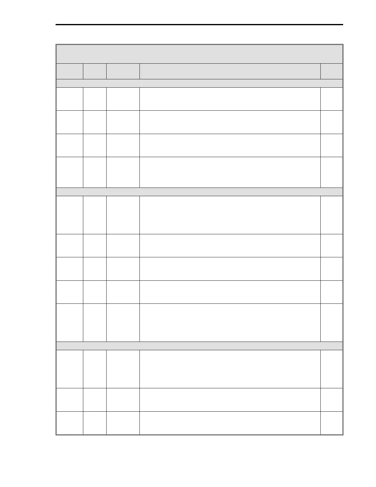
Table 15-3. CS41 Four Loop Controller Datapoints
Data-
point Table Module Title and Function
De-
fault
AI3 - Remote Setpoint Loop 2 (Is affected by Setpoint Related Datapoints) (Cont)
C279 5-4 AI3 Engineering Zero - Enter a value that represents in
engineering units the Loop 2 Remote Setpoint lower range
signal value.
0
B272 5-4 AI3 Digital Filter Index - This is a first order filter that can be
applied to the Loop 2 Remote Setpoint signal. See Table 5-4
for input values.
3
L419 5-4 AI3 0-5 V Input - Enter a value that matches the signal voltage
range of the Loop 2 Remote Setpoint signal. 1 = 0 - 5 V
input range; 0 = 1 - 5 V input range.
0
L443 5-4 AI3 Square Root Signal - It is used if the Loop 2 Remote Setpoint
input is a squared signal value that must be linearized. 0 =
input is already linear; 1 = square root to restore linearization.
0
AI4 - Process Variable Loop 3
C260 5-4 AI4 Engineering Span - Set to 100 by CS41; however, it can be
changed. Enter a value, that when added to the Engineering
Zero value, will produce an upper range value in engineering
units that represents the Loop 3 PV transducer upper range
signal value.
100
(CS41)
C280 5-4 AI4 Engineering Zero - Enter a value that represents in
engineering units the Loop 3 PV transducer lower range
signal value.
0
B273 5-4 AI4 Digital Filter Index - This is a first order filter that can be
applied to the Loop 3 PV transducer signal. See Table 5-4
for input values.
3
L420 5-4 AI4 0-5 V Input - Enter a value that matches the signal voltage
range of the Loop 3 PV transducer. 1 = 0 - 5 V range; 0 = 1 -
5 V range.
0
L444 5-4 AI4 Square Root Signal - It is used if the Loop 3 PV transducer is
a nonlinear differential pressure (DP) cell that provides a
squared signal value. 0 = input is already linear; 1 = square
root to restore linearization.
0
AI5 - Process Variable Loop 4
C261 5-4 AI5 Engineering Span - Set to 100 by CS41; however, it can be
changed. Enter a value, that when added to the Engineering
Zero value, will produce an upper range value in engineering
units that represents the Loop 4 PV transducer upper range
signal value.
100
(CS41)
C281 5-4 AI5 Engineering Zero - Enter a value that represents in
engineering units the Loop 4 PV transducer lower range
signal value.
0
B274 5-4 AI5 Digital Filter Index - This is a first order filter that can be
applied to the Loop 4 PV transducer signal. See Table 5-4
for input values.
3
3 of 13
Section 15. CS41 - Four Loop Controller
15-11