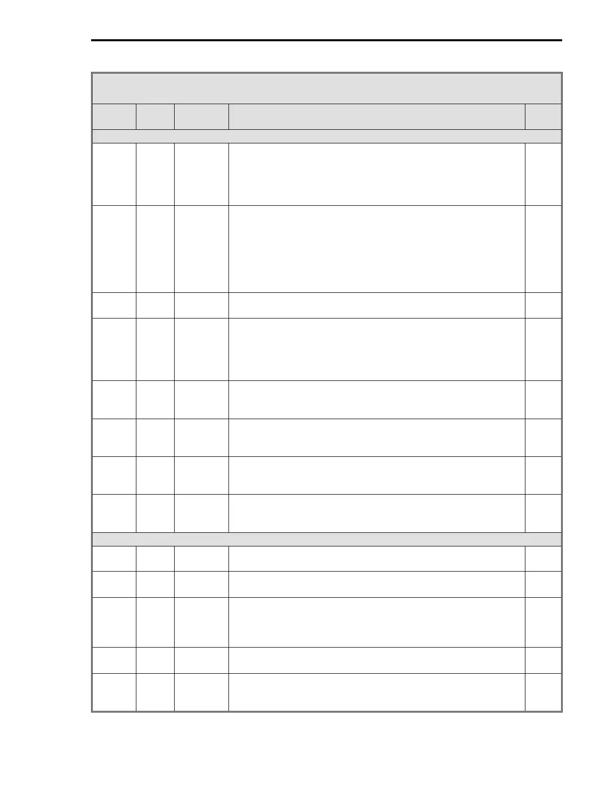
Table 15-3. CS41 Four Loop Controller Datapoints
Data-
point Table Module Title and Function
De-
fault
AI7 - Remote Setpoint Loop 4 (Is affected by Setpoint Related Datapoints)
L187 5-9 CON3 Remote Setpoint Enable - This datapoint is controlled by
CCI3. When CCI3 is a closed contact, this datapoint is set to
1 to allow the modified Loop 4 Remote Setpoint to become
the value used as the control setpoint if the R/L push button
is in Remote.
0
C220 5-9 CON1 Remote Setpoint Bias (B1) - This datapoint and Remote
Setpoint Ratio (K1) allow the Remote Setpoint input to be
modified by the Setpoint Generator.
Setpoint = [Remote Setpoint X Ratio] + Bias
SP = [RSP X K1] + B1
The B1 and K1 datapoints are modified when the input signal
must be scaled to match the setpoint range desired.
0
C221 5-9 CON1 Remote Setpoint Ratio (K1) - See Remote Setpoint bias (B1)
above.
1
C263 5-4 AI7 Engineering Span - Set to 100 by CS41; however, it can be
changed. Enter a value, that when added to Engineering
Zero, will produce an upper range value in engineering units
that represents the Loop 4 Remote Setpoint upper range
signal value.
100
(CS41)
C283 5-4 AI7 Engineering Zero - Enter a value that represents in
engineering units the Loop 4 Remote Setpoint lower range
signal value.
0
B276 5-4 AI7 Digital Filter Index - This is a first order filter that can be
applied to the Loop 4 Remote Setpoint signal. See Table 5-4
for input values.
3
L423 5-4 AI7 0-5 V Input - Enter a value that matches the signal voltage
range of the Loop 4 Remote Setpoint signal. 1 = 0 - 5 V
input range; 0 = 1 - 5 V input range.
0
L447 5-4 AI7 Square Root Signal - It is used if the Loop 4 Remote Setpoint
input is a squared signal value that must be linearized. 0 =
input is already linear; 1 = square root to restore linearization.
0
AO0 - Control Output Loop 1
L472 5-5 AO0 0-20 mA Output - 0 = 4-20 mA signal; 1 = 0-20 mA signal.
Enter a value to match the Loop 1 output valve requirements.
0
L120 5-9 CON0 Manual Fallback Disable - 0 = always power up in manual for
Loop 1; 1 = auto/manual selector unchanged at power up.
0
L122 5-9 CON0 Hard Manual Limit - 1 = apply output limits to the final output
of the Loop 1 Auto-Manual Generator. Affects both the
manual push buttons and the controller’s result. 0 = do not
apply limits.
1
C109 5-9 CON0 Output High Limit - Sets maximum Loop 1 Control Output
signal value for in engineering units.
100
C110 5-9 CON0 Output Low Limit - Sets minimum Loop 1 Control Output
signal value in engineering units.
0
5 of 13
Section 15. CS41 - Four Loop Controller
15-13