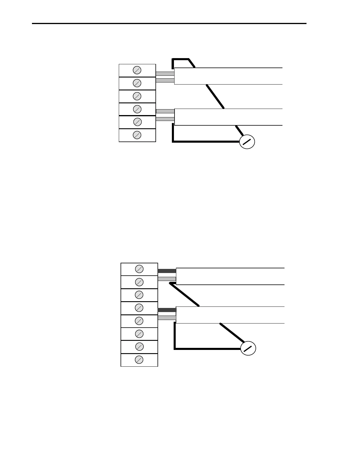
Figure 2-25. Current Input Signals to AI0&1 (Transmitters Have Power
Source)
Figure 2-26. Current Input Signals to AI0&1 (Transmitters Receive +24
V dc from Controller)
PIN 2 AI0
PIN 4 +24 VOLTS
PIN 3 SIGNAL COMMON
PIN 5 AI1
TB1
CABLE FROM TRANSMITTER
CABLE FROM TRANSMITTER
NO. 6
SCREW
CHASSIS SAFETY
GROUND
WIRED AS SHOWN EACH TRANSMITTER HAS ITS OWN POWER SOURCE AND DOES
NOT REQUIRE +24 V FROM THE CONTROLLER
PIN 6 SIGNAL COMMON
+
-
+
-
PIN 3 SIGNAL COMMON
PIN 5 AI1
PIN 4 +24 VOLTS
TB1
CABLE FROM TRANSMITTER
CABLE FROM TRANSMITTER
NO. 6
SCREW
CHASSIS SAFETY
GROUND
WIRED AS SHOWN EACH TRANSMITTER RECEIVES +24 V FROM THE CONTROLLER
PIN 2 AI0
+
+
PIN 1 +24 VOLTS
-
-
53MC5000 Process Control Station
2-30