4 Repair
4.6.1. Replacement of motor, axis 1
3293HAC026876-001 Revision: F
© Copyright 2007-2010 ABB. All rights reserved.
Removal, motor axis 1
The procedure below details how to remove motor, axis 1.
Extension 300mm for
bits 1/2"
3HAC12342-1
Power supply - 24 VDC, max. 1,5 A
For releasing the brakes.
Standard toolkit - The content is defined in
the section Standard
toolkit on page 409.
Calibration Pendulum
toolkit
3HAC15716-1 Complete kit that also
includes operating
manual.
Other tools and
procedures may be
required. See
references to these
procedures in the
step-by-step instruc-
tions below.
These procedures include
references to the tools
required.
Circuit Diagram See the chapter Circuit
diagram.
Equipment, etc. Spare part no. Art. no. Note
Action Note
1.
DANGER!
Turn off all electric power, hydraulic and pneumatic
pressure supplies to the robot!
For Foundry Prime robots:
Do not turn off the air pressure to motors and SMB.
2. Remove the cover for connector access on top of
the motor by unscrewing its four attachment screws.
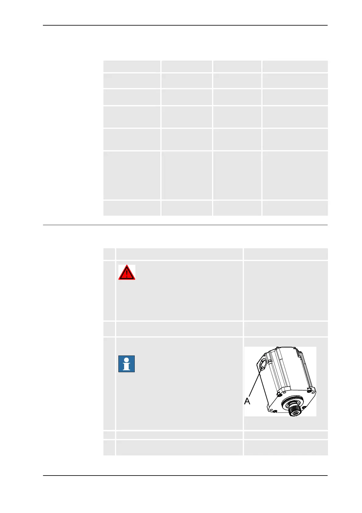
3. Remove the cable gland cover at the cable exit by
unscrewing its two attachment screws.
NOTE!
Make sure the gasket is not damaged!
xx0200000199
• A: Cable gland cover
4. Disconnect all connectors beneath the motor cover.
5. Apply lifting tool, motor axis 1, 4, 5 to the motor. Art. no. is specified in Required
equipment on page 328.
Continued
Continues on next page