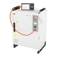
DeviceNet board connector (option)
xx0200000292
The following table shows the connections to the DeviceNet connector:
FunctionWire colorSignal nameI/O pin
DeviceNet network negative power ( 0 V)blackV-1
DeviceNet communication network terminal
(low)
blueCANL2
Network cable shieldbareShield3
DeviceNet communication network terminal
(high)
whiteCANH4
DeviceNet network positive power ( 24 V DC)redV+5
Tip
The DeviceNet network needs to be powered by a separate 24 V power supply,
or the DeviceNet function will not work.
See Application manual - DeviceNet Master/Slave, 3HAC066562-001, section
"Hardware overview" for more information on how to connect 24 V to the
DeviceNet network.
For connection details, see Circuit diagram - OmniCore V250XT, 3HAC074000-008.
Continues on next page
102 Product manual - OmniCore V250XT
3HAC073447-001 Revision: B
© Copyright 2020-2022 ABB. All rights reserved.
3 Installation and commissioning
3.5.8 Descriptions for connectors
Continued

 Loading...