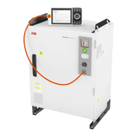
Required tools and equipment
NoteArticle numberEquipment
Content is defined in section
Standard toolkit for controller on
page 414.
-Standard toolkit
-ESD protective wrist band
Required documents
NoteArticle numberDocument
3HAC074000-008Circuit diagram - OmniCore
V250XT
Removing the HMI signal connector
Preparations
Note/IllustrationAction
DANGER
Before doing any work inside the cabinet,
disconnect the mains power. For more
information, see Electrical safety on
page 28.
1
Opening the door on page 176.Open the door.2
Location of wrist strap button:
ELECTROSTATIC DISCHARGE
(ESD)
The unit is sensitive to ESD. Before
handling the unit read the safety inform-
ation in section The unit is sensitive to
ESD on page 43.
3
xx2100000318
Removing the HMI signal connector
Note/IllustrationAction
Cut the cable ties and remove the cables
out from the clips in the cabinet carefully.
Note
Make records about the sequence that
cables are removed. The cables need to
be installed in the same position.
1
Continues on next page
Product manual - OmniCore V250XT 315
3HAC073447-001 Revision: B
© Copyright 2020-2022 ABB. All rights reserved.
5 Repair
5.3.3 Replacing the HMI signal (FlexPendant) connector
Continued

 Loading...