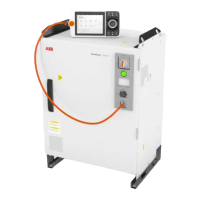
LEDs on the main computer:
xx2100001068
Detailed working procedure
NoteAction
LED Module status should be
green.
• If not, see Troubleshooting
the power unit on page 382.
• If the power unit is ok, check
that incoming mains is well
connected and that the in-
coming mains switch is
turned on.
Check Module status LED on power unit A1.1
LED PS should be green.
• If not, see Troubleshooting
the power unit on page 382.
• If the power unit is ok, check
that the power inlet is prop-
erly connected and the
power inlet switch is turned
on.
For more details about the LEDs,
see Troubleshooting the robot sig-
nal exchange proxy on page 405.
Look at the LED PS.2
LED MS should be green.
• If not, see Troubleshooting
the robot signal exchange
proxy on page 405.
Look at the LED MS.3
LED PC and LED HMI should be
green.
• If not, see Troubleshooting
the robot signal exchange
proxy on page 405
Look at the LEDs PC and HMI.4
For more details about the LEDs,
see Troubleshooting the main
computer on page 398.
Look at the LEDs PC PWR, PC HDD, and PC
STAT.
5
If the drive unit status LED is not
lit, see Troubleshooting the drive
unit on page 376.
Check the drive unit status LED.6
If the problem remains, contact ABB.7
Tip
For more details, see Circuit diagram - OmniCore V250XT.
Product manual - OmniCore V250XT 359
3HAC073447-001 Revision: B
© Copyright 2020-2022 ABB. All rights reserved.
7 Troubleshooting
7.2.2 Start-up failure
Continued

 Loading...