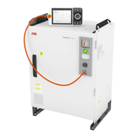
LEDs
The illustration below shows the indication LEDs on the drive unit.
xx2100001069
DescriptionName
The status indicator LED can be used to
identify the following status during star-
tup/power on:
• Red, steady: Default when power is
available.
• Red, flashing (~1Hz): Power is on, self-
test is ongoing, operating system is
loading.
• Green, flashing (~1Hz): Application is
loaded and waiting for communication.
• Green, steady: Drive unit is operation-
al.
If the LED does not turn steady green after
30-60 sec, the status indicator LED can be
used to identify the following issues:
• No color: Power to the drive unit is
missing.
• Red, steady: Internal error.
• Red, flashing (~1Hz): Firmware error
or self-test failure.
• Green, flashing (~1Hz): Communica-
tion error to another module.
MS (Module Status) LEDA
Continues on next page
Product manual - OmniCore V250XT 377
3HAC073447-001 Revision: B
© Copyright 2020-2022 ABB. All rights reserved.
7 Troubleshooting
7.3.3 Troubleshooting the drive unit
Continued

 Loading...