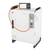
• FlexPendant is placed in its holder with the emergency stop device hidden
behind the emergency stop device cover.
xx1800000553
DescriptionNamePin
Reference ground towards 24 V.0V_CH1_CH21
24 V power, provided by robot controller, for
ES channel 2 only.
24V_CH22
Negative side of external emergency stop
input, channel 2.
ES2-3
Positive side of external emergency stop in-
put, channel 2.
ES2+4
Negative side of external emergency stop
input, channel 1.
ES1-5
Positive side of external emergency stop in-
put, channel 1.
ES1+6
Reference ground towards 24 V.0V_CH1_CH27
24 V power, provided by robot controller, for
ES channel 1 only.
24V_CH18
Reference ground towards 24 V.0V_CH1_CH29
24 V power, provided by robot controller, for
AS/GS channel 2 only.
24V_CH210
Negative side of AS/GS input, channel 2.AS2/GS2-11
Customer needs to connect these pins to the
reference ground of 24 V power.
Positive side of AS/GS input, channel 2.AS2/GS2+12
Customer needs to connect these pins to a
24 V power.
Negative side of AS/GS input, channel 1.AS1/GS1-13
Customer needs to connect these pins to the
reference ground of 24 V power.
Positive side of AS/GS input, channel 1.AS1/GS1+14
Customer needs to connect these pins to a
24 V power.
Reference ground towards 24 V.0V_CH1_CH215
24 V power, provided by robot controller, for
AS/GS channel 1 only.
24V_CH116
Continues on next page
Product manual - OmniCore V250XT 93
3HAC073447-001 Revision: B
© Copyright 2020-2022 ABB. All rights reserved.
3 Installation and commissioning
3.5.8 Descriptions for connectors
Continued

 Loading...