ABB | SACE Emax 2
Electronic accessories | 2 - Ekip Measuring modules
167 | © 2013 ABB | 1SDH001000R0002 - L7804
Connections
The modules must be mounted directly on the Mainboard, to the right of the release. In parallel
they are connected to a connector, to which the phase and neutral voltages arrive on the
internal contacts of the circuit-breaker, or on the external sockets.
Information on the assembly is available from the web site http://www.abb.com/abblibrary/
DownloadCenter/, in particular with the kit sheet 1SDH001000R0505.
IMPORTANT: in the case of dielectric tests, you need to disconnect the modules
as illustrated in the assembly diagram, and to disconnect the external socket-
outlets from the terminal box. It is not necessary to remove the modules.
Wiring diagrams for the modules are provided below, with and without an isolation transformer:
YO
01
H4
02
K5
04
K10K9
94
92
H3
9181
H2
82
K4
K8
8474
K7
K3
H1
72
7161
HC
62
HC
64
54
52
51
Trip Unit I/O
HC
K6
Ge-
Ge
Szc
K2
K1
W4
W3
R2
R1
Q4Q3Q2Q1YC2YC
YU
YO2
RTC
I/O
TU
44
42
41
34
32
31
24
22
21
14
12
11
C22
C21
C12
C13
C11
C2
C3
C1
D2
D1
48
46
45
Ne
Rca
Ne-
Gzi
Szo
Szi
Gzo
Rct
Vn
V1
V2
V3
U2
U1
38
36
35
98
96
95
YRMS33S51
EKIP Signalling 4KQ5..Q10
Module Module Module
EKIP Supply
20
V1
V1
V2
V2
V3
V3
VN
VN
L3L2L1N
XV
XV
A4
X
A1
X
A4
L1 L2 L3
VN
VN
V3
V3
V2
V2
V1
V1
N
21
Ekip Measuring Pro
Ekip Measuring
Ekip Measuring Pro
Ekip Measuring
MEAS
K51 K51
MEAS
L3L2L1N
A3
B3
a3
b3
A2
B2
a2
b2
TU1
A1
B1
a1
b1
23
Ekip Measuring Pro
Ekip Measuring
MEAS
K51
VN
VN
V3
V3
V2
V2
V1
V1
E)
*
Ekip Measuring Pro
22
V1
V1
V2
V2
V3
V3
VN
VN
L3L2L1
K51
MEAS
L3L1 L2
GS
PE
3~
Diagrams 20 - 21 - 22 - 23
Further information is available on page 156, or on the site http://www.abb.com/abblibrary/
DownloadCenter/, where the wiring diagram is available 1SDM000091R0001.
Access from the display
With the release energized, the presence of the modules activates the following on the display:
• Additional graphical pages, that display measurements.
• Additional menus.
The additional graphical pages are:
• A summary of the measurements in progress (maximum phase current, maximum phase-
to-phase voltage, power factor, and the active, reactive and apparent power), accessible
from the page Histograms (see page 61).
• The indicators of the maximum phase-to-phase voltage and of the active, reactive and
apparent power, accessible by selecting the pages Measuring instruments (see page 63).
• The measurements of the phase and phase-to-phase voltages, and of the active, reactive
and apparent power, as well as the energy meters, accessible by selecting the pages
Measurements (see page 64).
• The history of the minimum and maximum phase-to-phase voltages and maximum and
mean powers, accessible from the menu Measurements (see page 72).
• The wave forms and the harmonics of the phase-to-phase voltages, accessible from the
menu Measurements.
The additional menus allow you to:
• Configure the protections activated by Ekip Measuring Pro.
• Configure the modules.
• Display the measurements associated to the modules (in addition to those displayed in
the graphical pages).
• Display information on the modules.
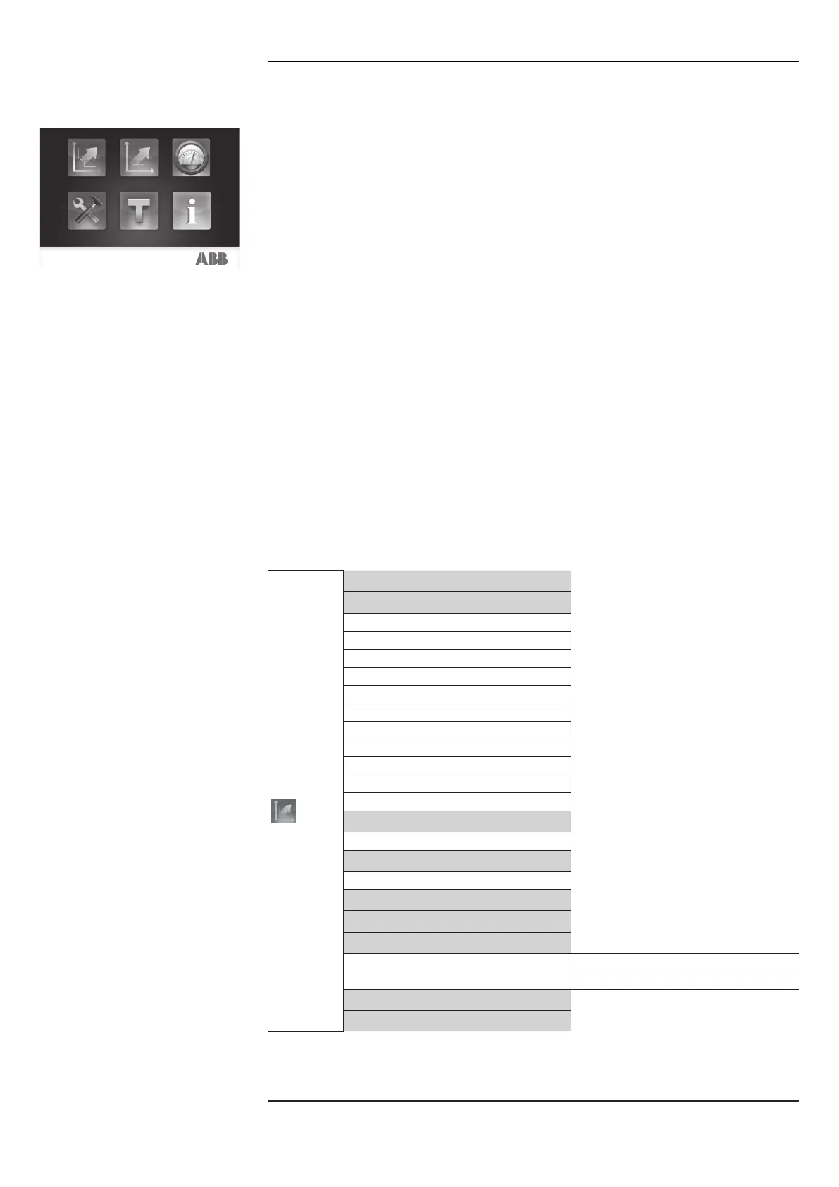
The following table illustrates the path from the display to access the configuration parameters
of the protections activated by the Ekip Measuring Pro module:
Advanced
…
IU Protection
RC Protection
(1)
Protection UV
Protection UV2
Protection OV
Protection OV2
Protection RV
Protection VU
Protection UF
Protection UF2
Protection OF
Protection OF2
Protection ROCOF
Protection RP
Protection RQ
Protection OP
Protection OQ
Protection UP
Syncrocheck Protection
Signallings
Phase Sequence
Cos φ
Current thresholds
…
(1)
Protection available with Rating Plug RC and Ekip Measuring Pro modules, and external differential toroid
or RC (see the menu Settings, Circuit-breaker, Earth protection), and alternative to the Gext protection (see
the Protections menu).
Continued on the next page

 Loading...


