34
9.4 Displays / messages
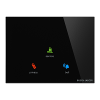
Fig. 23: Displays
Display Function Action of the device
21,0°C
Controller switched on /
display of set-point
temperature
Comfort mode
– Heating/cooling is at the normal level.
– The display is only visible when the
"Superimposed operating mode" is active.
(Local operation is blocked)
Standby mode – The heating/cooling output is slightly lowered.
Dew point mode
– The room temperature in not lowered any
further.
Frost protection mode
– The temperature is kept above a minimum
value.
Heat protection mode
– The temperature is kept below a maximum
value.
Condensate
– The condensate tank is full. The device
operates in heat protection mode.
OFF
– The control is deactivated. The device
operates in frost protection mode.
ECO mode
– The heating/cooling output is extremely
lowered.
Heating/cooling switchover – Manual switchover.
1
3
Fan speed levels 1-3 – Manual ventilation control.
A
(3)
Automatic fan speed levels – Automatic ventilation control.
Window contact
– The control is deactivated. The device
operates in frost protection mode.
Table 3: Overview of displays