144
>High Pass: HP. Allows frequencies above the cutoff point to
pass through i.e. rejects those below the cutoff point
> Band Pass: BP. Allows frequencies close to the cutoff point
to pass through i.e. simultaneously rejects those above and
below the cutoff point
> Band Stop: BS. Rejects frequencies close to the cutoff point
(within a certain “band”) i.e. allows frequencies above or
below the cutoff point to pass through. Note that Resonance
(see “Resonance” on page 141) effectively narrows this
band, making the effect less obvious.
Note that filter 2 does not offer “Analog” modes.
Key Follow
Accessible from the panel via SHIFT + ENV AMOUNT when
filter 2 is selected.
> 0 to 127: How much cutoff 2 follows the MIDI note and pitch
bender. See “Key Follow Base” on page 145. Modulation
destination “Filter2 Key Follow”.
Env Polarity
>Positive, Negative: The effect of Env Amount on filter 2 cut-
off can be inverted by setting this parameter to Negative.
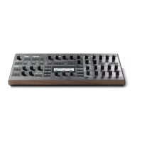
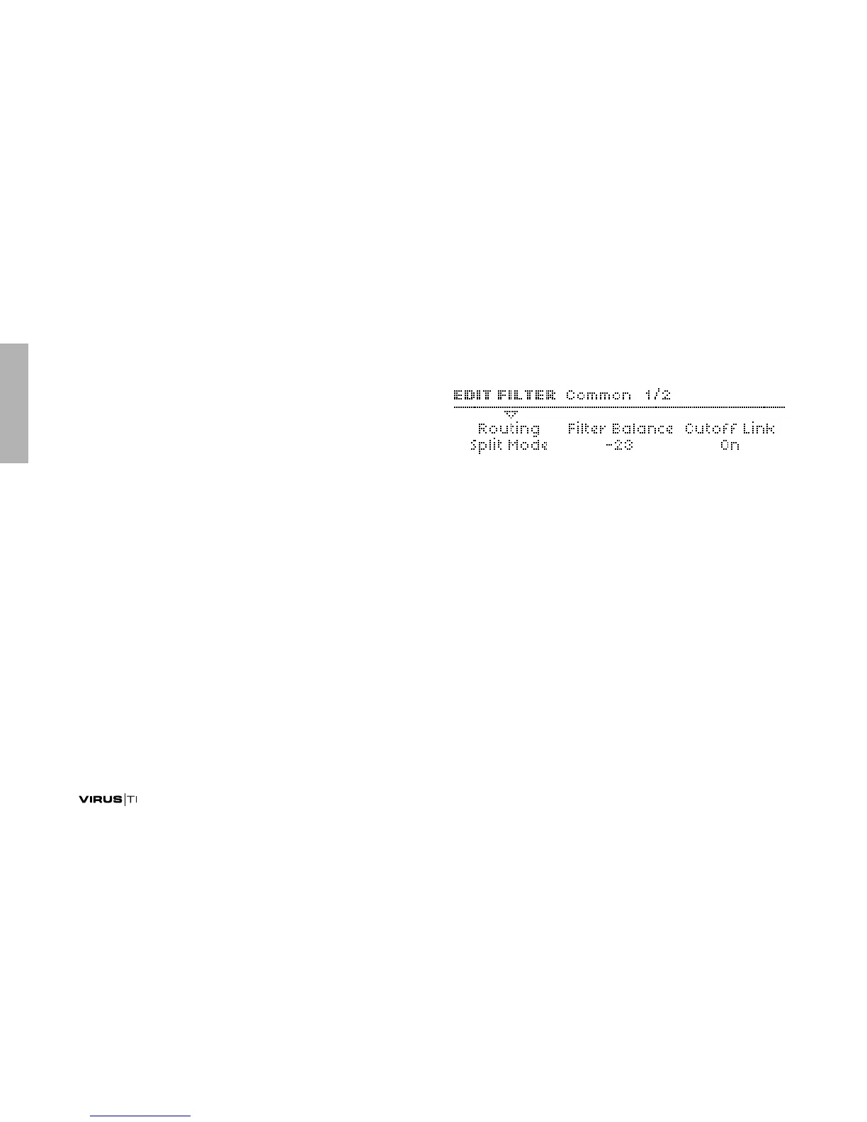
Common
Routing
There is no difference between Serial 4 and Serial 6 if one of
the “Analog” filter modes is selected (see “Mode” on
page 142).
> Serial 4: The filters are routed in series, with 2 poles (see
glossary) each.
> Serial 6: The filters are routed in series, filter 1 has 4 poles
and filter 2 has 2 poles.
>Parallel 4: The filters are routed in parallel with 2 poles each.
> Split Mode: The filters are also routed in parallel with 2 poles
each, but each filter receives a different set of signals: Oscil-
lator 1 and the sub-oscillator are sent to filter 1, oscillator 2
(including FM), oscillator 3 and noise are sent to filter 2. The
ring modulator is disabled.