Chapter 2 - Safety
22 Adept Cobra s600/s800 Robot User’s Guide, Rev H
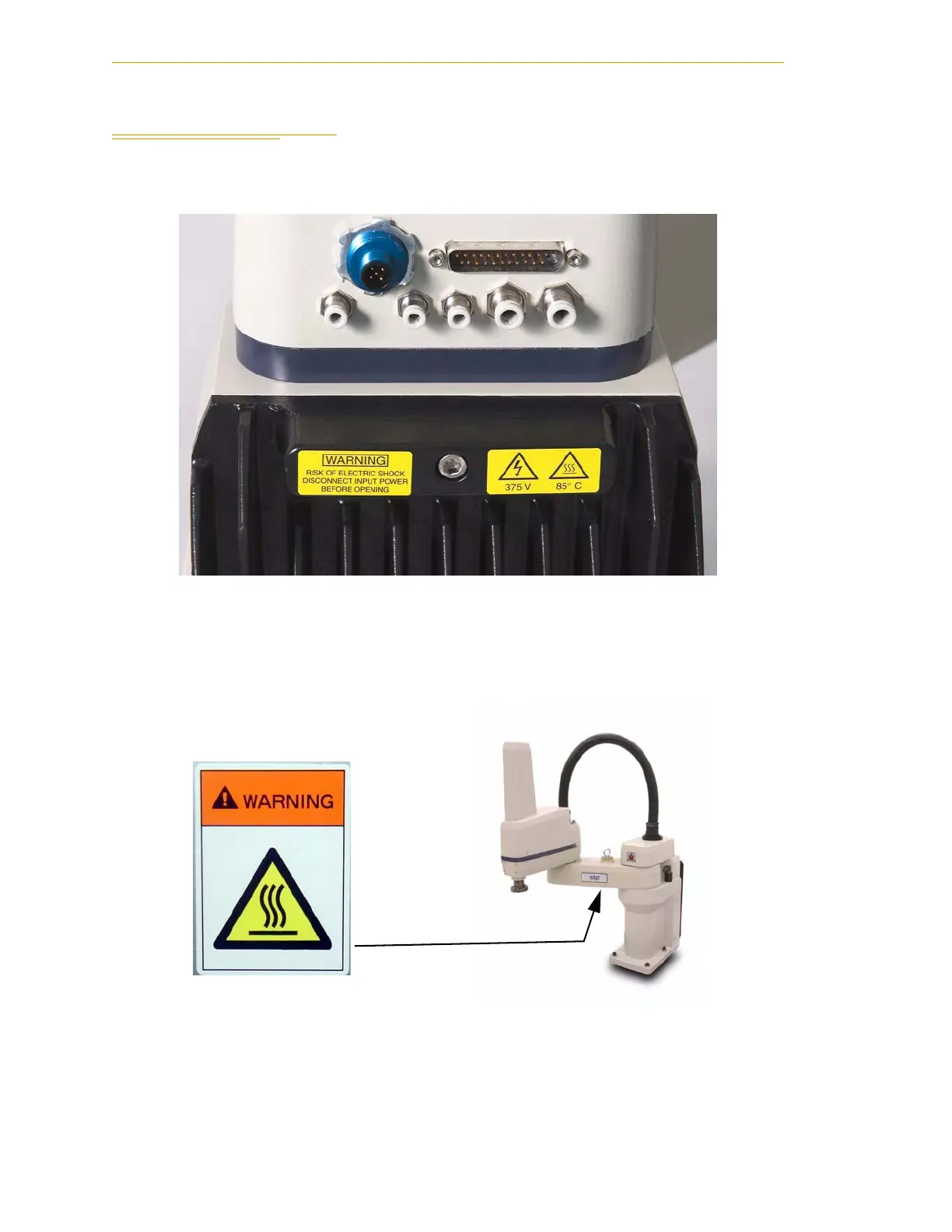
2.2 Warning Labels on the Robot
The following two figures show the warning labels on the Adept Cobra s-series robots.
Figure 2-1. Electrical and Thermal Warning Labels on AIB Chassis
Figure 2-2. Thermal Warning Label on Underside of Inner Link
 Loading...

